Continue to Site

Welcome to EDAboard.com

Welcome to our site! EDAboard.com is an international Electronics Discussion Forum focused on EDA software, circuits, schematics, books, theory, papers, asic, pld, 8051, DSP, Network, RF, Analog Design, PCB, Service Manuals... and a whole lot more! To participate you need to register. Registration is free. Click here to register now.

Injected current filter

Status
Not open for further replies.

neutrino

Member level 2
Joined
Jul 3, 2004
Messages
44
Helped
0
Reputation
0
Reaction score
1
Trophy points
1,286
Location
Italy
Activity points
236
I have a problem with the test "Injected current" (under standard 61000-4-6).
The source of disturbance (AM wave modulated), is injected along the 115 Vac power line and propagates along the entire chain of supply (+12 V, +5 V and GND) of PCB. I tried to filter it with a common mode inductors, capacitors and low-pass filters, but without a minimum result. What can I do?
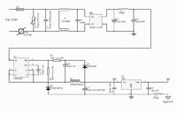
 

Can you post your schematic? It's kinda hard to tell anything without schematic


+5V is connected to digital microcontroller circuit


+5V is connected to digital microcontroller circuit


Given your schematic, it looks like:

a) you have no caps to a 'ground' in and around your filter (ahead of your rectifier)

b) on each incoming AC cycle, alternately one side then the other of your incoming 'line' voltage is connected to your circuit 'ground' symbol; common for an off-line no-transformer switcher

c) given a) and b) above, it looks like you have a "direct connection" (except for a series inductor) from your input AC 'line' to your circuit ground.


The solution might be properly-rated capacitors to the 'ground' up in and near the filter inductor, besides just the Line-to-Line capacitors (which are needed for EMI coming out of the power supply back towards the AC line).

I have looked at standard 61000-4-6 in this document for a quick review of your referenced standard:

"Pitfalls and practice of IEC 61000-4-6 conducted immunity testing"
**broken link removed**


Hope some of this helps in resolving your EMI immunity testing.

Jim
 
Thanks Jim. I used Y capacitors (4.4nF) from each line to GROUND (product chassys). I used many filter in well-know configurations, with many cells (low pass, common and differential mode). But without variations. The injected current is common mode in each power line and should go from AC power line to low voltage microcontroller. Then back to the source, using capacitive coupling with ground large metallic reference. But i don't understand why filter has no effect, independently of filter tipology. The frequency that causes fault in electronics (touch control board), is a very low frequency (500KHz)

Thanks for the link. I know elmac.co.uk and this application note, that i red sometimes because is well made.

Hmmm .. it sounds like you have a difficult case. It may come down now to board and 'ground' layouts ... are you familiar with the 'star' connection technique for establishing a common circuit ground?

I offer this paper which offers some insight into designing for immunity, in this case to lighting, which is also a kind of 'low frequency' content type of upset pulse:

http://www.infineon.com/dgdl/AN-PS0...d24f8&fileId=db3a304412b407950112b4182a8224f9

A webpage with a good example of layout and also additional filter topologies:

Achieving EMC for DC-DC Converters


Also Freescale has a good pdf app note titled:

"Improving the Transient Immunity Performance of Microcontroller-Based Applications"

**broken link removed**

Is it possible that the RF for immunity testing is getting into the microcontroller via means other than directly in the SMPS?

Jim
 
Last edited:
Thanks Jim !!! This case is very strange. The receptor is capacitive touch. At 600KHz there aren't radiated pohenomena, so i filtered every channel with low pass filter. I used a single point ground, even GND trace guard. I connect to microcontroller only Vcc and GND, but the fault is the same. So i Filtered 5V and VCC with small common mode inductor (2x1mH). Nothing.

A strange things happen. Injected current test (sandard EN 61000-4-6), inject current that flow in common mode on the circuits and back to the source using stray capacitance with SHIELD plane on the floor. If i try to move away PCB from SHIELD (1meter instead 0.1m), the capacitance decreases, so noise should decreases consequently. This does not happen...

I am reading the Infineon AN, the other two i read few years ago.

thanks for the great help Jim !!!
 

Status
Not open for further replies.

Part and Inventory Search

Welcome to EDABoard.com

Sponsor

Back
Top