Continue to Site

Welcome to EDAboard.com

Welcome to our site! EDAboard.com is an international Electronics Discussion Forum focused on EDA software, circuits, schematics, books, theory, papers, asic, pld, 8051, DSP, Network, RF, Analog Design, PCB, Service Manuals... and a whole lot more! To participate you need to register. Registration is free. Click here to register now.

Ingco MMA16015 welder control module

simce

Full Member level 4
Joined
Jan 9, 2004
Messages
214
Helped
12
Reputation
24
Reaction score
12
Trophy points
1,298
Activity points
2,477
Hi,
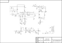
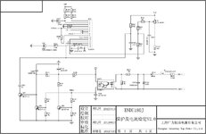
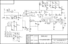
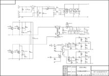
I'm looking for welder control module pin description and if possible schematic of the module from attached picture. The welder is currently overshooting set current and on currents below 90A the output current is not steady but fluctuates quite significantly. This "behavior" is seen even when the welder was new, but now i'm getting annoyed since I'm having difficulties weld thin metal.

I'd like to get information how control board operates and hopefully disable hot start and force arc features which i believe are making the issues.

Thanks.
WIN_20240216_14_32_47_Pro.jpg
 
Hi,

Please show the PCB where it is mounted and describe what this module is meant to control...
Why do you think this is defective?


Klaus
 
The module controls mini REL welder Ingco MMA16015.

It is most likely design flaw since there are others reporting that the set current on display is not accurate and deviates 10-20%. That's not an issue, it is annoying that when the current is set below 90A is not steady but fluctuates 5%-40% during the welding (measured and confirmed with current measurement clamp). This makes the welder almost useless on welding thin metal. I'd like to try to fix this issue.

Thanks.
IMG_20240216_162020.jpg
IMG_20240216_162108.jpg
 
Hi,

so the welder is not defective,
but you want to fix a design flaw.

I think it´s much more difficult, because you need to find the path for the whole control loop.... and find out why there are the fluctuations come from and how to fix them.
It may be a timing problem, maybe noise is intrduced, maybe a software problem, a hardware problem, a control loop adjustment ...

***

If you don´t have a shematic and tools to follow the signal path.... it´s just a trial and error method ... maybe with the result to really kill some devices.

Sadly I guess I can´t help you on this.

Good luck

Klaus
 
OK, so it's an "inverter" welder and that means a feedback control
loop, which means potential instability. But that might or might not
be a defect. Current control can be freaked by things like poor ground
clamp electrical contact (maybe low current does not suffice to "weld"
the ground clamp to the workpiece and the oxidation if present can
present weird behaviors like negative differential resistance, which
in a load can be destabilizing).

I have a big multiprocess welder, a fine imported tool, and its current
-setting- is flaky (delivered current then wanders about that setpoint).
I'm not good enough at welding for this to be the dominant problem.
 
The welder is currently overshooting set current and on currents below 90A the output current is not steady but fluctuates quite significantly
What you mean with overshooting?, set current above the selected value?

What model and brand of the welder?, how many ampere is the welder?
 
Hi,

so the welder is not defective,
but you want to fix a design flaw.

I think it´s much more difficult, because you need to find the path for the whole control loop.... and find out why there are the fluctuations come from and how to fix them.
It may be a timing problem, maybe noise is intrduced, maybe a software problem, a hardware problem, a control loop adjustment ...

***

If you don´t have a shematic and tools to follow the signal path.... it´s just a trial and error method ... maybe with the result to really kill some devices.

Sadly I guess I can´t help you on this.

Good luck

Klaus
I have the tools, and can make the schematics (during today I've identified a schematics which seem almost identical to what i have, hmm I'm not allowed to share a link), but there are too many unknowns to me why the selected solution is chosen and why the control module has so many pins and what is their purpose.
In my opinion the instability of welding current comes from faulty Arc force feature which is needed to keep steady arc when welder is not keeping constant distance between the electrode tip and welding material. This feature detects increase of distance and increases the welding current to keep a constant arc. However, when low current is used the increase of the current is too large and happens sporadically which makes the problems.
 
Have you tried to turn off the arc stabilization (?) to see if your hand
can learn to pick up the slack instead?

What it's evidently meant to fix, is so variable (user by user, current
setting by setting, workpiece and ground, yadda yadda) that maybe
you'd be better off "going bare" and learning the feel.
 
There's no control on front plate to control arc force, and I'm not sure which part od the control logic is doing this "feature". I'm assuming that there's a pin on control module for this purpose.
Here attached are diagrams from similar welder. Any help in identifying arc force is welcomed.
 

Attachments

  • resanta220-shema4.jpg
    resanta220-shema4.jpg
    118.4 KB · Views: 38
  • resanta220-shema3.jpg
    resanta220-shema3.jpg
    99.2 KB · Views: 39
  • resanta220-shema2.jpg
    resanta220-shema2.jpg
    120.7 KB · Views: 36
  • resanta220-shema1.jpg
    resanta220-shema1.jpg
    149.1 KB · Views: 41
There is only one Pot which is on schem3 which must be for some wide tolerance such as transformer and supply variation parameters.

The board is maze of RC's + BJT's with quad Op Amp and a PWM regulator.

So I would look at how to reduce the starting PWM to reduce surge or steady current or increase sensitivity with 100 pF series cap across the R034 feeding CS=ISENSE and try to also scope VF=VFB. using twisted pair AWG 30 magnet wire to 10:1 probe.


1708201661392.png
1708201583400.png
1708201134057.png
 
Last edited:
Thanks Tony,
pot3 is used to set nominal welding current. What i suspect is the arc force control is the feedback circuit after GOO3 on schematics 3. Not sure if complete disable by shortening output of GOO3 will happen, will try and share results.
I'll start scoping different signals and will share details.
p.s. Vfb in this device is connected to gnd, and the current sense and set point goes via dedicated circuit to pins 1 and 3 of pwm control chip.
 
having difficulties weld thin metal.
I've had experience with oxy-propane and arc welding. The welder was AC type, adjustable up to 200 A. I tried to weld sheet metal, but I was unsuccessful. I always vaporized the workpiece. I tried thick and thin welding rods (new rods are essential). I tried low and high current settings.

I have a hunch the arc was too intense and lasted too long. You might find a way (a circuit) to make an arc that lasts a brief moment. Something as quick as an automatic tack welder.

Picture thin work as a fusible link which can tolerate several Amperes. Or stranded lamp cord which flashes briefly when short circuited. The loose strands turn into a bead of copper. Your welder has to avoid doing the same. I think the arc has to turn off within milliseconds, to leave the work intact.
 

LaTeX Commands Quick-Menu:

Part and Inventory Search

Welcome to EDABoard.com

Sponsor

Back
Top