Continue to Site

Welcome to EDAboard.com

Welcome to our site! EDAboard.com is an international Electronics Discussion Forum focused on EDA software, circuits, schematics, books, theory, papers, asic, pld, 8051, DSP, Network, RF, Analog Design, PCB, Service Manuals... and a whole lot more! To participate you need to register. Registration is free. Click here to register now.

infra-red liquid level detector

Status
Not open for further replies.
infrared water level detaector

oh no!!!! my lecturer sd i must not use dat circuit i posted bt must get a new design to the same specifications...................!!!!:( what is this gal to do.

Im gna start from scratch like i neva saw that circuit b4, wen i come up with somethang useful il ask 4 guidance
 

water level detector project circuit

IR absorption of water and many other liquids is good point. But I still think, that a lot of other issues are contradicting an industrial use. Without a problem specification, the discussion is more or less hypothetical.
 

liquid level detection laser reflexion

FvM said:
IR absorption of water and many other liquids is good point. But I still think, that a lot of other issues are contradicting an industrial use. Without a problem specification, the discussion is more or less hypothetical.
That's right.
We are discussing a theoretical model only.
However, it's useful for the topic author to clearify his problem specification.

Added after 26 minutes:

fantabulous68 said:
oh no!!!! my lecturer sd i must not use dat circuit i posted bt must get a new design to the same specifications...................!!!!:( what is this gal to do.

Im gna start from scratch like i neva saw that circuit b4, wen i come up with somethang useful il ask 4 guidance
Your teacher's quite right! :D
This design has some weakness, for example the IR receiver-amplifier (OPAM) may be suturated with any input photo-signal, so this OPAM inputs should be biased at some positive voltage. I think it's better if you use PD in photo-conducting mode with a positive bias voltage (5-12V) at the cathode and a load resistor (some K ohm) connected between PD anode and ground. Then the pre-amplifier should be designed as a trans-impedance non-inverting high gain circuit.
I've got a proximity detector design for your reference. See attached file.
Note that's not tested and basically designed for solid surfaces!!!!
Good lucks.
 

electronic liquid level sensor

Saturation current is mainly a matter of load resistance. It's basically similar in photoelement and photoconducting mode. The main advantage of photoconduction mode is higher bandwidth, almost meaningless with a few kHz modulation. On the other hand, photoelement mode doesn't offer any advantage in AC light detection.

The shown circuit uses a remote control receiver IC. It's generally not suited for CW mode of operation. It's optimized for pulse signal transmission with a maximum base band pulse width. Also the receiver AGC doesn't allow to set a defined threshold.

I see options for circuit improvement in a different regard: A synchronous detector at the receiver can provide a better supression of AC light interferences.
 

infrared water level

the ir receiver
incorporates a receiver, an amplifier and a very reliable filter that rejects all the signals that are a couple of kilohertz far from the original central frequency, all in one single integrated circuit, just as big as a 5V regulator. The central frequency is fixed by the constructor usually at 40 khz.


The electronic circuit for this proximity sensor is shown in figure 2.A, as you can see it is composed of two main parts, the sender and the receiver. The sender part is composed of the four NAND gates, the 2N2222A transistor and the IR LEDs. The first two gates are a NAND gates oscillator, they generate the 40 Khz square wave required to send valid signals that are compatible with the receiver IC. The second two gates are configured as one single AND gate, used to enable or disable the sender part. The potentiometer R1 adjust the current injected into the LED thus it controls the strength of the emitted IR beam and thus it controls the range of the proximity sensor. The potentiometer R2 is used to precisely adjust the frequency of the signal that drives the IR LED.

The Receiver is pretty simple, because is basically relies on the U2 the IR receiver is discussed above. The low pass RC filter composed of R6 and C2 is very important to eliminate the noise especially that the emitter and the receiver share the same power supply. Noting that the output of U2 (the IR receiver) is active low, it is clear that the LED D2 will glow when an object is detected by the sensor.


how can i modify the circuit to detect if the target is in a pre-defined range from the detector?

Added after 14 minutes:

thers the circuit
 

infrared liquid level sensors

FvM said:
Saturation current is mainly a matter of load resistance.
I'm fraid that in the top posted Author design, any low photocurrent generated by PD forces OPAM-amplifier saturated with output voltage always 0V (Gnd). Interchanging PD Anode /Cathode connections may fix this mistake.


FvM said:
The shown circuit uses a remote control receiver IC. It's generally not suited for CW mode of operation. It's optimized for pulse signal transmission with a maximum base band pulse width. Also the receiver AGC doesn't allow to set a defined threshold.

For simple intensity detection (compairison with fix thresold), IR LED pulse-mode is more effective than CW and it's also compatible with the receiver. AM CW mode is better for phase detection variant.
Distance (level) alarming thresold can be set (tunned) if the LED current limit resistor (in trasmitter side) is replaced by a variable one.

FvM said:
I see options for circuit improvement in a different regard: A synchronous detector at the receiver can provide a better supression of AC light interferences.
Thanks for an idea.

Added after 4 minutes:

fantabulous68 said:
how can i modify the circuit to detect if the target is in a pre-defined range from the detector?

You look at your post again! :D
R8 !

Added after 6 minutes:

@fantabulous68
Normally, drop voltage for LED in forward current is about 1.6-1.7V. So 3 serial connected LED may require drop voltage more than the supply voltage (5V).
 

ir level detector

I'm fraid that in the top posted Author design, any low photocurrent generated by PD forces OPAM-amplifier saturated with output voltage always 0V (Gnd). Interchanging PD Anode /Cathode connections may fix this mistake.
No, it's just fine as connected in the circuit.

Regarding IR-LED modulation with remote control receiver IC TSOP1838 (or any similar device), I was refering to the shown circuits, that provide a 38 kHz square wave. According to the data sheet, a constant 38 kHz background signal is suppressed by the AGC circuit.
 

liquid level sensor circuit

thanx so much for the feedback all!!!mwah...

"Distance (level) alarming thresold can be set (tunned) if the LED current limit resistor (in trasmitter side) is replaced by a variable one."

the 2nd posted cct uses a variable resistor in the transmitter side.

MY Question:
Can i use the transmitter in the 2nd cct i posted
for my project???

Added after 7 minutes:

***@fantabulous68
Normally, drop voltage for LED in forward current is about 1.6-1.7V. So 3 serial connected LED may require drop voltage more than the supply voltage (5V).***

sorry, im a bit confused. why do u mention 3 leds
Thanhlongbin??
 

water level controller contactless sensors

fantabulous68 said:
thanx so much for the feedback all!!!mwah...

"Distance (level) alarming thresold can be set (tunned) if the LED current limit resistor (in trasmitter side) is replaced by a variable one."

the 2nd posted cct uses a variable resistor in the transmitter side.

MY Question:
Can i use the transmitter in the 2nd cct i posted
for my project???

Added after 7 minutes:
Not yet! The receiver module TSOP1838 is designed for PCM communication.
You have to put an additional Modulating signal to Control Port (CTRL) in the transmitter side. Download the receiver data sheet to get modulating signal format.

In receiver, you need to add some Low Pass filter to Vout port, then a comparator (look like your 1-st post). Or you can build a pulse LPF by NE555 (like my proposed reference).

fantabulous68 said:
***@fantabulous68
Normally, drop voltage for LED in forward current is about 1.6-1.7V. So 3 serial connected LED may require drop voltage more than the supply voltage (5V).***

sorry, im a bit confused. why do u mention 3 leds
Thanhlongbin??
Oh yes! Sorry, there're 2 LEDs only. I have to replace my glasses. :D
 

oil drop on infrared sensor

The CTRL input in the figure, stands for Control, and this pin should be connected to the source of the low duty cycle pulses discussed above, whether it is a microcontroller or an LM555 timer that generates the pulses.

Somebody please tell me if im visualizing the final TEST setup of this infra red proximity circuit correctly.


should i construct a stand to mount the detector directly above the tank??? any ideas, drawings please. i did this in paint.

could sum1 suggest a better way?
 

infrared sensor water level

I didn't notice the CTRL input. It actually allows to use the TSOP sensor. I don't want to predict the achievable accuracy and level repeatability. You should better test it empirically.

Obviously, the sensor won't work at exactly zero distance, at few centimeters offset should be used.
 

detect infrared level in sunlight

1) any1 recommends the use of a circular barrier surrounding the led(transmitter side) for noise immunity?

Added after 1 minutes:

circular black plastic tube.


2) what functions/modules can the synchronous detector be broken down into?
 

infrared red level sensor

FvM said:
I'm fraid that in the top posted Author design, any low photocurrent generated by PD forces OPAM-amplifier saturated with output voltage always 0V (Gnd). Interchanging PD Anode /Cathode connections may fix this mistake.
No, it's just fine as connected in the circuit.
.
No, FvM
The mentionned PD-OPAM connection is fine if OPAM is supplied by 2 voltage : positive and negative relative to GND level.
But in this design, OPAM has single supply only. (12VDC and GND).
More detail:
Say
-Ip: Input photocurrent ;
- U+,U- : Input voltage at OPAM;
- Uout: OPAM Output volatage. 0V < Uout < 12V for 12VDC single supply.
- R: resistor between U- and Uout.
=> Uout = "U-" - Ip*R.
Because U- = U+ = 0V (GND)
=> Uout = - Ip*R <0 with any Ip!!!! This contradicts with supply condition.
That why I said OPAM may saturated.

Added after 31 minutes:

fantabulous68 said:
1) any1 recommends the use of a circular barrier surrounding the led(transmitter side) for noise immunity?

Added after 1 minutes:

circular black plastic tube.


2) what functions/modules can the synchronous detector be broken down into?
1. Your IR receiver has FOV (Field of View or angle of view) about 50-60 degree. If the tank is too tall, or its bottom is too small, the reveiver may be affected by reflected beam from the tank walls that causes a fault alarm. For this case, a circular black plastic tube can reduces the PD FOV.
Some infor. for "the black tube":
Say:
-R, D : tank bottom radius and tank heigh.
-Rt, Dt : tube radius and legnth for cylinder tube.
Rt/Dt should < R/D. You can choose Rt/Dt = 0.5* R/D if the detector is fixed in the center of tank top.
Generally, in certain detector position, looking throu the tube, you must see only the part of tank bottom.

The tube inside surface should be harsh to prevent secondary reflection.
2. The synchonous detector variant is not simple. First, you try asynch. one .
 

the design must:

indicate the liquid level in a container using infrared.

EG. if the container has 10cm height of liquid in it, THEN the design must display the level


" 10cm level"
**********************************************************************
the rest of the specifications:
The design should be useful in liquid level or proximity detection. It should operate by detecting the distance from the target by reflection of an infra-red beam. It should safely detect the level of a liquid in a tank without any contact with the liquid itself. The device's range should be variable, from a couple of cm. to about 50 cm.
**********************************************************************

i will need to display the level, hence i have to use a microcontroller:lcd/2 7segment displays.


does any1 have a circuit and code which uses a pic microcontroller/stk500??
that would be useful in this project plz refer me to the links. thanks
 

liquid detector device

Believe it or not...
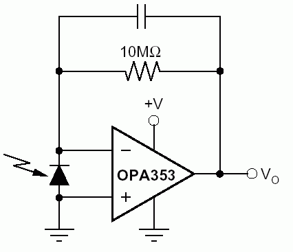
From a TI data sheet. Obviously a rail-to-rail OP is required.
90_1248513477.gif
 

external liquid level detection

FvM said:
Believe it or not...
From a TI data sheet. Obviously a rail-to-rail OP is required.
90_1248513477.gif
I want to believe so much! But Google book says:
"When Photodiode (PN or PIN) used in zero bias or photovoltaic mode, the flow of photocurrent out of the device is restricted and a voltage builds up. The diode becomes forward biased and "dark current" begins to flow across the junction in the direction opposite to the photocurrent. This mode is responsible for the photovoltaic effect, which is the basis for solar cells—in fact, a solar cell is just a large area photodiode."
You can check it by simple measurement. I did it once and got about +300mV at cathode/anode pin in sunlight!!!
I think, this TI data sheet mainly descripts the OPAM functions.

Added after 22 minutes:

fantabulous68 said:
the design must:

indicate the liquid level in a container using infrared.

EG. if the container has 10cm height of liquid in it, THEN the design must display the level


" 10cm level"
**********************************************************************
the rest of the specifications:
The design should be useful in liquid level or proximity detection. It should operate by detecting the distance from the target by reflection of an infra-red beam. It should safely detect the level of a liquid in a tank without any contact with the liquid itself. The device's range should be variable, from a couple of cm. to about 50 cm.
**********************************************************************

i will need to display the level, hence i have to use a microcontroller:lcd/2 7segment displays.


does any1 have a circuit and code which uses a pic microcontroller/stk500??
that would be useful in this project plz refer me to the links. thanks
Hi,
It seems to be that you do not understand what FvM and I wrote !!
All the designs you proposed (1-st, 2-nd,..) has the same distance detection principle. This principle can not give you the answer how much the distance (or level) is! The result is boolean value : True or False. It means the tank is full or not! That's why this design called proximity detector.

From the the specifications you've just updated above, I guess You need a distance meter in rangce 50cm ! If so, first forget about MCU and 7-segment display and please read again all the thing FvM and I said in page 1 of this topic.
 

infrared water level

Perhaps other forum members, that also have built similar circuits can comfirm it's correct operation. I'm not sure, if you misunderstood photodiode or OP operation.

As my last explanation attempt: As long as the OP cicrcuit is operating in linear range, the photodiode is zero rather than forward biased. The photo current flows from OP output through the conversion resistor into the cathode - the current polarity is the same as in reversed bias PD operation.

If the photo diode would be forward biased, the negative voltage at the inverting OP input causes a positive voltage at the output and a current flow that cancels the photodiode voltage.
 

pic liquid level infrared

FvM said:
Perhaps other forum members, that also have built similar circuits can comfirm it's correct operation. I'm not sure, if you misunderstood photodiode or OP operation.

I'm a graduated physics. PD operation is base knowledge in the semi-conduction course. My 20 years experience in practics electronics give me some thing to do with OPAM. :D

FvM said:
As my last explanation attempt: As long as the OP cicrcuit is operating in linear range, the photodiode is zero rather than forward biased. The photo current flows from OP output through the conversion resistor into the cathode - the current polarity is the same as in reversed bias PD operation.

No. It's not fine!. Only with reversed bias for Si-PD about 5V PD can generate photocurrent that flows into cathode and go out from anode.
In your example circuit, PD is zero-biased or some mV between OPAM inverted and non-inverted inputs. In interation with incoming into P-N junction photons the PD generates positive charges (holes) at N-layer (cathode). So PD becomes a photocell and it can generate a current in an external closed circuit. Sometime this current called "Photocell-current".
Photocell-current and photocurrent are different types. It's not hard to understand if you're familar with so called Fermi level in P-N junction.

Photocurrent or photocell-current is reason to create a current through the conversion resistor then the OPAM output voltage is a consequencial result . This is also a base knowledge of OPAM operation! :D
 

infra red tank level sensor

I basically don't understand what you want to tell me. Seems like you are starting a new photo diode theory. But whatever you mention in this regard, it doesn't change the fact, that the shown basic circuit is operating fine. You say, the PD must be reversed to make it working. Obviously, one opinion is right and the other wrong. I think, the question can be answered by a simple test (or correct usage of semiconductor theory). I'm not motivated to add more arguments now.
 

experiment of infrared water level detector

Yes, we should cool down. You may expect, however, a correct answer to your questions.

For those, who want to understand, why the PD current has the same polarity in reversed bias and zero biased mode, I suggest a Vishay publicationhttps://www.vishay.com/docs/80086/physics.pdf
Figure 12 I-V-Characteristics of an Si Photodiode under Illumination visualizes the diode behaviour.
 

Status
Not open for further replies.

Similar threads

Part and Inventory Search

Welcome to EDABoard.com

Sponsor

Back
Top