Continue to Site

Welcome to EDAboard.com

Welcome to our site! EDAboard.com is an international Electronics Discussion Forum focused on EDA software, circuits, schematics, books, theory, papers, asic, pld, 8051, DSP, Network, RF, Analog Design, PCB, Service Manuals... and a whole lot more! To participate you need to register. Registration is free. Click here to register now.

Industrial Grade Robust Inverter Build Thread

Status
Not open for further replies.
Today I tested the hard wired deadtime circuit, and it was a 10 min task. The only time it took was getting the proper Resistors and Caps from the store. I mean it is so damn simple to get deadtime in hardware, I can't believe why people are so reluctant about it. Yes space is an issue, but it's not as complicated a circuit as we make it to be in our heads. All you need is a Resistor, a Cap, a high speed diode and a few NOT gates, which also double up as buffers btw.
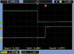
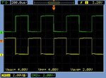
NewFile0.jpgNewFile1.jpg

As you can see, getting 1.2us deadtime. This will be later fine tuned using a precision Pot in the final circuit.

It's nice as all you need from the controller are the signals for the top or bottom 3 switches and you get the signals for the remaining switches along with dead time as the output. Thus you can literally use an Arduino for V/F.:grin:
 

I'm now thinking of turning to the thermal shutdown system.

Never used a thermistor in my life so need help. I think the first thing should be package/shape and mounting (how and where).

Please throw some light on the subject.
 

OK I'm stuck at precharge now. Totally stuck.

As you know this is a general Inverter module for college labs. Thus the DC link voltage will be different every time. So the simple logic of setting the relay when voltage exceeds say 90% of rated value cannot work.

I thought of setting it after the voltage across the charging resistor reduces to a small value but then it will be zero when the control supply turns on and before the power to the DC Link has been applied. As soon as the power supply is turned on, the voltage will develop across the charging resistor and if above said logic is used, the already ON relay will try and break the current which is an absolute NO-NO.

What to do? Many of you may have had such inverter modules in your college/R&D labs. What is the system used in such Test Bench Inverter Modules?
 

555 timer that closes the relay 0.5 - 1.0 sec after power up to the timer Vcc
 

I also want to go for flip flop for proper and complete shutdown. But which one. RS I presume. Thinking on it. The fact that the output is indeterminate in some cases is scaring me. .

I doesn't have to be that way. You can do a simple poweron reset circuit. If you are using something similar to the 4013 which has a reset-on-high input do as follows:
-connect a 0.1uF capacitor from the reset pin to Vdd.
-connect a 100k resistor from the reset pin to ground.
-you can avoid this last component, but for best reliability, add a 1N5711 diode in parallel with the capacitor, cathode towards Vdd.
 

555 timer that closes the relay 0.5 - 1.0 sec after power up to the timer Vcc

But I'll need to have 2 separate power sources for the inverter, 1 for the control circuits which will provide clean power at 15V, 12V, 5V to all the protection, precharching, driver circuits etc, and the other will provide power to the power circuit and charge the DC bus. The second one will be variable according to the users needs and type of motor/load right from 12V to 650V.

The user obviously will turn on the control circuit first and then the power circuit. From what moment do I reliably measure the 0.5 to 1sec?

One solution I can think of is to have a minimum DC Link voltage, say 12-15V and the timer starts counting after this value is exceeded. Thus the system works even if the module is being supplied directly from the wall, or through a dimmer. (I think:-|)
 

I've been waiting for parts and hence no updates for the past few days. I was looking over IGBT modules on element14 and am baffled by IGBT selection for inverters.

https://www.edn.com/design/analog/4371295/Teardown-The-nuances-of-variable-frequency-drives

I saw this article, which is an excellent read btw, and from what I can see, it is a Schneider VFD which is 2.2kW and they have used a 35A IGBT module. Why?

According to my calculations, 2.2kW will require 2200/(1.732x230) = 5.5A. Do we really need a switch rated at close to 7 times this value? Or is it because even the cheapest IGBT module has that rating? So if an IGBT module is rated at say 10-20A, what rating inverter can it be used for?
 

What is the start current of a typical motor? 5 - 7 times the run current for a SCIM, these things an inverter designer needs to know....
 

I was afraid someone would say that:sad:. See I was hoping that all the starts for a VFD are going to be soft starts by default, slowly increasing V/f or in case of FOC, it will be even better.

But then this means that we need to be prepared for direct 415V 50Hz start.
 

So you are going to limit the performance of the system (i.e. start time) with your inverter - competition any one? The igbt/heatsink combo will easily handle start currents for the 5 sec or so needed to start - integration of power requirement and heatsink...!

- - - Updated - - -

Also you are just asking for blow ups if you use small igbt's.....!
 

Two questions:
1) I was ordering the following gate driver and DC-DC converter to go with it.

https://in.element14.com/avago-technologies/hcpl-3120-000e/optocoupler-2-5a-gate-drive-o/dp/9995439

https://in.element14.com/xp-power/itb0515s/dc-dc-converter-15v-0-0667a-sip/dp/2475857

The FGA25N120 IGBT I want to test things with has a total gate charge of 200nC so I suppose above to components should be more than overkill (Please confirm). Each of the six drivers will have their own dedicated DC-DC converter.

I'm using such isolated board mount DC-DC converters for the first time so wanted to know whether there is something special which must be connected at either the input or output for it to work properly. I've decided to add 6.8uH and 4.7uF as an EMI filter at the input. Is a simple 10-22uF cap along with 0.1uF ceramics OK for the output or is an LC filter essential (especially considering the application)? My basic question is do such converters require components at input and output like say LDO regulators which must have proper input and output capacitors for proper and stable operation.

2) The other thing I've been thinking about over the past few days is to add an Atmega8 on this Inverter module which will take care of all protection, precharge, thermal etc. The code in it will be damn small, like if any fault input is raised, disable all gate inputs, precharging delay etc. I've read that uCs are susceptible to getting reset and malfunctioning and so protection circuits should be hard wired in the form of logic gates but in the end don't all inverters eventually disable gate outputs on the controller level in the form of FAULT interrupts etc. Your thoughts please.
 

Any over current protection needs to be damned fast to be effective.
Servicing an over current interrupt is not going to get the job done.

You need a fast direct acting hardware shut down, and think in terms of hundreds nanoseconds, not in tens of microprocessor machine cycles.
 

Down here at learner level, I have put a pathetic NPN 2N2222A wired as inverter from an adc over-range pin to a regulator enable pin as over-current/over voltage shutdown, that works...sort of, my problem is that the adc starts measuring again asap ;) - not an issue on my circuit, just needed an LED to flash to let me know more than 2V input to adc and cut out the supply to a DUT quickly (even if only for a second, grrr). The 2N2222A is 320 nanoseconds from Rise to Fall (according to datasheet), but I'm also using old-fashioned glass fuses for hard-wired over-current shutdown/ turn-off. FF ideal, but I could only get F grade fuses...
 

Often, the fastest way to stop the escalating drama is the shut down pin on the IGBT gate drivers.

Software (at its leisure) can then light a fault lamp, start up the beeper, and begin some kind of soft start, gentle recovery process.

One way to quickly blow fuses is with an SCR crowbar circuit.
Violent and nasty, but the fuse will surely pop pretty smartly.

Ideally there should be several layers of protection that can operate independently.
 
  • Like
Reactions: d123

    d123

    Points: 2
    Helpful Answer Positive Rating
That's what I'm saying Warpspeed, High speed comparators will shutdown the IGBTs for a few hundred microseconds. This is because I don't want to do the whole latching/holding/flip-flop thing using digital circuits.

The same signal will simultaneously be sent to the Atmega which will hold that fault condition, keep the IGBTs turned off and can have all the other alana-falana-adrak-lasun logic as to how long the inverter remains in fault state, how it gets cleared (Manual push button or preset delay), glowing appropriate Fault LEDs etc.

This is because I'm developing this as a general purpose inverter module for labs and so the user can completely skip the FAULT part from his code and all those things will be on the module itself by this sort of 'co-processor'.

What say you?
 

OK we got side tracked from question 1, i.e. DC-DC Converters and is output filter essential or will a 10-22uF be good?
 

Vfd are started slowly keeping V/f constant as frequency is ramped up for example 20-60 seconds. FOC usually has torque limitation that is typically set to nominal motor torque so you can accelerate agains torque limit. Nominal torque means about nominal current. Not 5 times nominal. There is no need to prepare for direct online start currents.

- - - Updated - - -

There are intelligent power modules from about 5 A upwards. They are made for small pwm drives. For example IRAMS series from International rectifier,

http://www.irf.com/product/Motor-Control-Gate-Driver-Intelligent-Power-Modules-IRAM-High-Voltage-3-Phase-Driver-with-IGBTs/_/N~1nje2t

At least few other manufacturers make similar modules.

So if an IGBT module is rated at say 10-20A, what rating inverter can it be used for?

If you use purpose made power module like IRAMS it is best to look it's datasheet. There is no fixed relation for the inverter rating vs. power module rating. For example cooling arrangement and switching frequency affects to available current. For 10 A IRAMS module () RMS phase current is 10 A when case temperature is 25C and 5 A when case temperature is 100C. Effect of used switching frequency to available output current is shown on the curves on the datasheet.
 
Last edited:

@tsan500, Exactly my thoughts and that Schneider drive I mentioned really confused me. Why 35A for 2.2kW drive was something I couldn't understand. Scalar or Vector, start is always going to be soft. Anyhow, we'll cross that bridge when we get there.

Right now I have to make a major policy decision regarding placement of DC Link Caps. Here's my initial layout.

New Bitmap Image.jpg

It's a simple 6 x TO-3P package IGBT 3-ph bridge with 2.5A Avago optocoupler drivers. I'm aiming for 2-2.5kW and this inverter is just to test out all my various circuits designed over the past few weeks like OC/SC shutdown, Over temperature shutdown, capacitor precharge etc.

I know the biggest factor relating to inverter design is DC loop inductance. So ideal placement of the bulk caps is as close as possible to the bridge. But take a look at this 2.2kW Schneider I mentioned earlier. It's bulk caps are away from the inverter board and connected to it by a twisted pair link. I am extremely tempted to place my DC link caps on a separate board with the rectifier, precharge resistor and relay etc.

My question is, if I keep the length of that twisted wire less than 2-3" and twist them real nice, can it be acceptable? This other board will basically act like a standalone 560-600V DC supply. What say you guys?

And yes I am placing these 0.47uF polypropylene film caps right next to each half bridge connected between the collector of the top switch and the emitter of the bottom. (Please confirm that these are the right caps used for IGBT decoupling).

**broken link removed**

I hope the gate loop isn't too huge. The space you see between the driver and the IGBTs is for the above mentioned decoupling caps.

- - - Updated - - -

And don't worry, final board will be all smd. I just wanted this one to be quick to make and populate.
 

Hi,
Some words, hopefully of wisdom.

* Layout is everything. You need as little inductance between your DC link and DC snubber caps across the DC terminals of the module. This minimizes overshoot across the devices when they interrupting a large fault current.

* Proper IGBT gate drive is also very important.

* When I design an inverter, I go through a set of tests that I call pulse testing. This ranges from using an inductor to take the DC link volts, normally 600 in my cases. This should then take about 100us to hit headline rating of the device. The inductor goes across one device and you switch the other device into it. You then let the current decay a bit, then switch on for a short period extra. You can then watch the commutation of the opposite diode and hopefully pick something up from this. Repeat test the other way round with upper and lower device transposed.

* The later test is to purposely cause a shoot through, such that the protection works, and your gate drive solution remains stable. The shoot through scenario is your worst case event. Most IGBT's have a 10us short circuit rating. Personally I test this at room temperature, and at the device externally heated to the devices headline rating, 150°C for instance. IGBT's tend to work quicker when they are cold. The faster the device switching, the higher the voltage spike when interrupting a large shoot through current. If your gate drives goes unstable during a shoot through, then clearly all bets are off.

* Use a gate drive circuit that has internal soft turn off so that the device Vge is reduced and then turned off. I am using an ACPL-302J in my latest design. This vastly reduces the voltage overshoot at turn off at shoot through.

When you have done your pulse testing then you will have confidence that the inverter will stand up to most things. I have used this method upto 300kW and produced a very robust and reliable inverter. Until you have done all these tests then you don't *really* know.

Test gear required: Isolated DSO eg Tektronix , pulse generator, high voltage bench supply. Good to have if the test gear can be remotely triggered/driven over LAN, particularly for bigger inverters. Don't fancy being anywhere near it if it lets go. My last job at 20mF of caps at 700V on the DC link so do the sums.

Hope that helps.

Two things. Please take a look at my previous post and the layout.

When you say a good gate drive, is what I have done OK?

When you say shoot through test, for how long (us) do I keep both turned on and how many times do I do this per second (i.e. frequency)?
 

Status
Not open for further replies.

Similar threads

Part and Inventory Search

Welcome to EDABoard.com

Sponsor

Back
Top