dr pepper
Advanced Member level 1

- Joined
- Mar 15, 2010
- Messages
- 428
- Helped
- 35
- Reputation
- 70
- Reaction score
- 41
- Trophy points
- 1,308
- Location
- lancs
- Activity points
- 4,171
Please help me understand this.
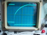
I have a test board for inductors and transformers so I can see at what charge time and current the inductor starts to saturate, the board just connects the inductor to the supply then disharges it into a diode, the voltage accross a current sense resistor in series with the supply is plotted on my 'scope, the fet gate drive is the x trigger.
I've been trying some larger new and salvaged cores and I've been getting some different readings, the charge current doesnt show up on the 'scope, the disharge does but not the charge.
Heres some bad pics of my 'scope, I have tried various combinations of time on/off for the fet gate drive, nothing seems to change, I thought at first the charge slope was just too slow for the 'scope sweep.
First pic, a 330uH test choke (on board the 'test bench'), second a larger choke that doesnt show the charge slope, and third the 'test bench. The lower trace is the gate drive for the fet, high being fet on:
Attachments
Last edited:
