Continue to Site

Welcome to EDAboard.com

Welcome to our site! EDAboard.com is an international Electronics Discussion Forum focused on EDA software, circuits, schematics, books, theory, papers, asic, pld, 8051, DSP, Network, RF, Analog Design, PCB, Service Manuals... and a whole lot more! To participate you need to register. Registration is free. Click here to register now.

inductor design for5 KW buck converter

Status
Not open for further replies.

Rajnaveen

Member level 2
Member level 2
Joined
May 11, 2014
Messages
42
Helped
0
Reputation
0
Reaction score
0
Trophy points
6
Visit site
Activity points
307
hi friends
I am designing a 5KW buck converter for battery charging from solar . will you pease help me in design .
how to select the core .? and i want it to operate in DCM is it better .how much inductence is sufficient .
 

Raj,

That's like asking how many foot pounds of torque do you need for an engine, without knowing the RPM range, input-output voltage and switching frequency ( which affects cost of switches but cheaper inductors)

By the way how many cylinders? I would suggest 3 minimum and maybe more.
 

Thank you Sunnyskyguy for your reply.
Sorry I forgot to mention :
Input voltage :100-170
Output Votlage:83-120
Switching Freq. 12KHz
Please provide me guidance for selecting Ferrite core and calculating inductance for DCM as well as CCM.
I need ur kind support.
 

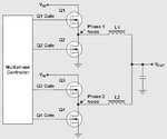
I'm in the design phase of a similar project (2kW solar charger) and I've choose a two-phase buck converter as a starting point (but you could use a multi-phase design).

dual phase buck converter.jpg

More informations here:

http://www.ti.com/lit/an/slyt449/slyt449.pdf

http://www.irf.com/technical-info/whitepaper/multiphasebuckapec03.pdf

http://www.onsemi.com/pub_link/Collateral/NCP4200-D.PDF

http://www.digikey.com/en/articles/techzone/2013/feb/the-advantages-of-designing-multiphase-highpower-buck-converters

This way, the inductor design it's much simpler (the output power will be distributed). Good luck!
 

Hello Red alert ,
Thank you for your suggetion . I will use this idea .
But I would like to ask you did you use 2 phase ? when 2KW can be made on single inductor only?
 

a multiphase converter will have huge benefits with less ripple current on the DC side with more headroom on saturating the cores, meaning much cheaper smaller cores but more of them with a net cost savings.

Minimum 3 phases.
 

Hello Red alert ,
Thank you for your suggetion . I will use this idea .
But I would like to ask you did you use 2 phase ? when 2KW can be made on single inductor only?

My 2kW charger has a low voltage output (24V) thus high current (80A) so I preferred to split it on two inductors. Anyway, the two(multi)-phase design has few other benefits (like described above).
 

"Sorry I forgot to mention :
Input voltage :100-170
Output Votlage:83-120
Switching Freq. 12KHz
Please provide me guidance "————————————— Where comes this spec. ? The 12KHz switching frequency is in the audible range of human, maybe it's 120KHz? The higher latter frequency makes the inductor smaller, but you cannot select much higher than that, and too high frequency is with more switching power loss which means less power efficiency.
 

"Sorry I forgot to mention :
The 12KHz switching frequency is in the audible range of human, maybe it's 120KHz? The higher latter frequency makes the inductor smaller, but you cannot select much higher than that, and too high frequency is with more switching power loss which means less power efficiency.

I was thinking about the same thing. A converter operating at 12 Khz will make an unbearable noise.
 

High power electronics is often operating in a 3 to 10 kHz range, dictated by a switching loss trade-off. E.g. most motor inverters in the higher kW range. They involve audible noise, if it's bearable depends...

For the requested low voltage and power range, switching frequencies above 20 kHz should be however feasible.
 

You are absolutely correct, multi-kilowatt power electronics do indeed switch at much lower frequencies, for a variety of reasons.

But usually the magnetic components in those circuits are fully potted or heavily impregnated with hard resin to alleviate the noise. These techniques are seldom available to the casual builder.
 

I would consider the most economical efficient inductor would be based around 1.5 to 2.0 Tesla laminated Cold Rolled Grain Oriented coated steel 0.3mm thick. Aka CRGOS. Look at microwave power transformers and rewind to suit turns ratio and consider power efficiency of 98% in the core is possible at the expensive of bulk and loss of watts per kg of CRGOS specs.

This design of 3 phase is suitable. **broken link removed**
 
Is it not possible to make it with 12 Khz ? Yes there will be sound from inductor but i think it is due to ferrite material . If proper ferrite material is not used inductor makes noise.
 

Magnetic forces of many Tesla will be impossible for newbie to suppress noise in vacuum impregnated Litz wire wound core.

the huge disadvantage of large ferrite is that unless you are familiar with non-linear permeability and thermal runaway, it can end in disaster at 5kW loads and losses rising from 200 to 500 Watts.

Ferrite is not very thermally conductive and hets lossier with temp rise, as does copper, while CRGO steel is better for staying cool with 100 Watts loss and forced air or oil bath to heat radiator.

It can be done, but you will fail on first few attempts with ferrite and winding methods.
 
Last edited:
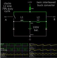
Taking a middle situation for supply V and output V...
Supply 135 V, battery 100 V.

Switching freq. 12 kHz. A little ways into continuous mode.

This demonstrates how twin interleaved buck converters might work, with a suitable value for inductors.


It is not necessary to add a smoothing/accumulating capacitor at the output.

The duty cycle will be adjusted to suit various supply V and battery V. For instance when supply is 170V and battery is 83V, duty cycle will be around 40%, and you'll be in DCM.
 
BradtheRad Thank u for that .

I want to know that what is relation between clk A and Clk B .I mean when will switch B put on after A . Is it complimentary to each other ?
 

Rajnaveen,

Are you sure your battery can bear near 60A continuous current? Every sort of battery has its appropriate charging algorithm, and over large current may lead over high temperature or even explosion. I'm not familiar about high volume batteries, and just a remind.
 

BradtheRad Thank u for that .

I want to know that what is relation between clk A and Clk B .I mean when will switch B put on after A . Is it complimentary to each other ?

"Clock A" and "Clock B" are identical but they are interleaved (2*PI/n phase delay, thus 180 degree for a two-phase converter).
 

BradtheRad Thank u for that .

I want to know that what is relation between clk A and Clk B .I mean when will switch B put on after A . Is it complimentary to each other ?

Leading edges are staggered evenly, 180 degrees (although they can be a few degrees off without hurting anything).

If you had 3 interleaved converters, leading edges would be spaced 120 degrees apart. Etc.

Duty cycle is a different parameter, of course. You would like to make one adjustment, and have it govern all converters.

As you can guess, things start to get interesting when you interleave 3 or more converters (which you might want to consider per post #6).
 

Bill66656 ,
Thank you,
We will use double battery bank of 300Ah

- - - Updated - - -

friends I am thankfull to all of you for your valuable suggestions .
Friends we are using an inductor for this buck converter is as follows:
Core EE10028
Inductance:150uH
But in this core when inverter section is at no load ; It is working well with ripple current of 12A. but when I put on the output of inverter , current wave of inductor become like a sine wave of 100Hz , I observed ripple current of 70A only at upper edge of that sine wave . Due to that ripple Inductor coil start heating and temp reaches to 80 deg cel in 2 hours. How to solve this issue ?
 

Status
Not open for further replies.

Similar threads

Part and Inventory Search

Welcome to EDABoard.com

Sponsor

Back
Top