Continue to Site

Welcome to EDAboard.com

Welcome to our site! EDAboard.com is an international Electronics Discussion Forum focused on EDA software, circuits, schematics, books, theory, papers, asic, pld, 8051, DSP, Network, RF, Analog Design, PCB, Service Manuals... and a whole lot more! To participate you need to register. Registration is free. Click here to register now.

Increase output on this circuit

Status
Not open for further replies.

nicholasdk

Newbie level 5
Newbie level 5
Joined
Mar 3, 2013
Messages
8
Helped
0
Reputation
0
Reaction score
0
Trophy points
1,281
Visit site
Activity points
1,348
Hi guys

I'm building some flashing led's for a portable sound system. I got this working so far: flashing leds to music when i play from the jack stick to my computer.
I ran in to some problems, when i connect my phone or ipod to the jackstick, the leds is not flashing. I therefore have some questions I think you can help me with.
First of all, why won't the leds flash when i connect my iphone instead of the computer?
I think is has something to do with the output of the iphone is smaller then the computer.
If this is the problem, is there some kind of thing to insert in the circuit between the tip31 and the jackstick in increase the output? If there is, can it be a variable, so it will be a kind of sensitivity, like a volume knop?

Secondly, I would like in install a switch to turn the whole thing on and off. I tink i'll need some kind of resistor here, but where in the circuit should it be placed? I placed it between the battery and the switch, is this correct?
Finally, how many ohms should the resistor have?

Here is the schematics of my circuit:
Skærmbillede 2013-03-28 kl. 17.45.37.png

I'm kinda new in this thing, I appreciate your help. :)
 

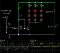
This circuit will light led's depending on the strength of the incoming signal:


A signal amplitude of 300 mV is shown here, which is comparatively low volume. (Typical line level is 1 VAC.)

The potentiometers will let you adjust led brightness to your desired range of operation.

A switch is placed in line with the battery terminal. There is no need for a resistor in series with the switch, since you have resistors in each led string.
 

Hi, thanks for your answer.
Of cause I have some questions back for you. :)

As far as i understand there is 2 potentiometers, which of them will control the brightness?
Shall the potentiometers be linar-mono of linar-stereo?

How many volt should the 10uf capacitor be?

Thank you again for your assistance..
 

Hi, thanks for your answer.
Of cause I have some questions back for you. :)

As far as i understand there is 2 potentiometers, which of them will control the brightness?

One pot sets the threshold at the bias of the transistor. The bias needs to be raised to about .55 V. Then the led's will just start to light when a soft audio signal comes through.

The other pot is your sensitivity adjust.

By the way, this circuit may cause distortion to an audio signal, because it draws current from it during one half of each cycle.

Shall the potentiometers be linar-mono of linar-stereo?

For a stereo signal you'll need two stereo pots.

How many volt should the 10uf capacitor be?

Thank you again for your assistance..

It should be rated to withstand the supply V, and then add some cushion to handle a strong incoming signal. Say 18V rating.
 

Thank you again.
I made this circuit, is this correct?
Skærmbillede 2013-03-29 kl. 22.25.46.png

I got this long, if you're interested:

Happy holidays
 

Attachments

  • Skærmbillede 2013-03-29 kl. 22.12.54.png
    Skærmbillede 2013-03-29 kl. 22.12.54.png
    54.3 KB · Views: 74

Thank you again.
I made this circuit, is this correct?
View attachment 88619

TIP31 is suitable to do the job.

* Switch around the wires to the base and collector.

* The capacitor should only be placed in the wire carrying the incoming signal.

* Although your method of tapping bias current below the load appears to work...

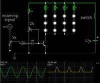
Notice that my schematic draws bias current directly from the supply, making for greater response.

- - - Updated - - -

Here is an updated schematic, since it appears you will use bright white led's. They have a higher forward voltage, hence you can use a lower safety resistance.


To run this schematic on your computer, and alter it to suit your purposes...

Click the link below. It will open the falstad.com/circuit website, and load his simulator java applet, with my schematic.

https://tinyurl.com/cd6pphl

To alter values, right-click on a component, and select Edit.
 

Hi again
I finally got the parts and put it all together.

But it stil dosent work...

It works with the pc plugged in, but the leds is flashing much weaker than before.

The one capacitor I could find is 10uf and 63v, could this be the problem? Should I find one with lower voltage?

If i connect it without the first pot 5k, 22ohm resistor and the capacitor, the leds are flashing as before, still only with a pc.

I'm currently working with this circuit: Skærmbillede 2013-03-30 kl. 16.19.52.png

Thanks again for your help :D
 

The one capacitor I could find is 10uf and 63v, could this be the problem? Should I find one with lower voltage?

That capacitor's values are fine. You need the capacitor to prevent DC bias current from travelling back into your computer or Ipod or phone.

As FvM points out, your schematic shows the transistor wired incorrectly.

And even though the LED's are oriented wrong on your schematic, you say they light up, so they must be oriented properly.

I think you are 90 percent of the way to success.

When you adjust the bias potentiometer, you should find you can make the LED's stay dark continually, or light up continually (although you should not exceed 20 mA, or whatever is their safe limit).

Somewhere in between those settings you should be able to make the LED's flash in sync with the music.
 
  • Like
Reactions: FvM

    FvM

    Points: 2
    Helpful Answer Positive Rating
Thanks for your help guys.

I got is to work this way: Skærmbillede 2013-04-11 kl. 20.34.47.png

Works, with iphone, ipod, computer, everything :D

I'll also upload some pics or a videoclip when I'm completely done building.
 

I just noticed that the LEDs need to be reversed. Also the bias circuit got disconnected in the latest schematic.
 

Status
Not open for further replies.

Similar threads

Part and Inventory Search

Welcome to EDABoard.com

Sponsor

Back
Top