Continue to Site

Welcome to EDAboard.com

Welcome to our site! EDAboard.com is an international Electronics Discussion Forum focused on EDA software, circuits, schematics, books, theory, papers, asic, pld, 8051, DSP, Network, RF, Analog Design, PCB, Service Manuals... and a whole lot more! To participate you need to register. Registration is free. Click here to register now.

Incandescent dash light dimmer question

Status
Not open for further replies.

Ryan Kamba

Newbie level 2
Joined
Mar 11, 2014
Messages
2
Helped
0
Reputation
0
Reaction score
0
Trophy points
1
Activity points
22
I have a cabin cruiser (boat) that I have just built a new dashboard for and installed all new gauges. Previously there was no dimmer switch for the dash lights. At night the old gauges were blinding while cruising. The new gauges are brighter yet, so I'm sure they'll be even worse.

Inside each gauge is a 12v 194 bulb (same style you'll find in an automotive dash or side courtesy light). These are regular non LED bbulbs.

My question is, can I just install a rheostat in the power supply wire? Or is it more complex than that?
 

If you are thinking about manage power directly through rheostat, no way.
Doing that, you´ll overheat it and burn at once.


+++
 

Ok, Thank you for the reply.

How would I make a dimmer for my dash lights? Or would you mind pointing me towards something that has been written up / discussed before.

Thanx in advance!

- - - Updated - - -

Just a thought. .. What about a potentiometer?
 

You could employ some adjustable step down SMPS converter.

Please inform wattage of the lamps, and how many ones you need to control, so that I´ll be able to estimate power requirements for such equipment.


+++
 

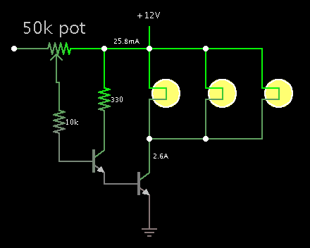
I think it uses 0.27A per bulb - so need to know how many bulbs. You can use a potentiometer WITH a transistor to control brightness.
 

This sounds similar to an automobile dashboard, where a single knob adjusts all bulbs. I'm pretty sure it is sufficient to use a single potentiometer and power transistor.

Too much current will burn up the pot contacts. So maybe a darlington arrangement is wise.

It is not necessary to reduce bulb voltage all the way to zero. They will get dim even with a few volts going through them.

5435426400_1394513249.png
 

just a few notes on the circuit so kindly shown by BradTheRed

the pot would be the linear type

the second transistor [which is connected to ground and directly to the bulbs] needs a heat-sink - how big depends on the current - how many bulbs.
 

The normal method is to use PWM driving a power transistor in the ground return of the lamp circuit. It should also run virtually cold at all brightness settings.
Look for simple 555 based PWM light controllers, there is no need for feedback circuits or regulators as all it has to do is dim the lights.

Brian.
 

Once OP mentioned such control project is expected to be embedded at boat, and also did not mentioned its dimension, I´m not too confident for propose any solution which would require an additional assembly step.

I believe an approach could simply give him specifications for an adjustable power supply, as a car dimmer : https://www.ebay.com/bhp/12-volt-dimmer-switch

Anyway. still lacks provide the total power consumption.


+++
 

Status
Not open for further replies.

Similar threads

Part and Inventory Search

Welcome to EDABoard.com

Sponsor

Back
Top