Dr. von Rosenstein
Member level 1

- Joined
- Feb 22, 2011
- Messages
- 41
- Helped
- 1
- Reputation
- 2
- Reaction score
- 1
- Trophy points
- 1,288
- Activity points
- 1,701
Hey all,
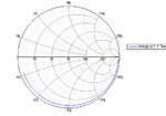
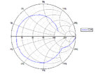
I have designed a 24 GHz full wave Greinacher-Rectifier (with diode connected transistors). Now I want to measure it’s impedance. But: The measured impedance deviates from the simulated impedance! The left picture shows my simulation results during a frequency sweep (100 MHz to 26.5 GHz). The right picture shows the measurement. The deviation at low frequencies seems acceptable. But I totally don’t understand the deviation at high frequencies (especially why the imaginary part is positive)! The simulation results are more or less coincide with values from literature.
I used for measuring an Agilent/Keysight N5242A PNA
www.keysight.com/en/pd-867173-pn-N5242A/pna-x-microwave-network-analyzer
with “Integrated True-Mode Stimulus Application”
https://www.keysight.com/en/pd-1416...ue-mode-stimulus-application-itmsa-option-460
https://na.support.keysight.com/pna/help/latest/Applications/iTMSA.htm#Create
For Topology I selected BAL-BAL and for Stimulus “Single Ended”. The right picture shows Sdd11 which I achieved with this settings.
Has anyone an idea where this deviation come from?
Do I have to do a “non linear measurement”? I do not have any experience with NVNA-Measurements. The problem is that additional devices seems to be needed (Measure Reference, Cal Reference, Splitter) which we had to buy first.
For clarity: The two differential HF-inputs of the rectifier are connected to Port 1 and Port 3 respectively. No output is connected with the VNA.
Thank you very much, and sorry about the English!


