Continue to Site

Welcome to EDAboard.com

Welcome to our site! EDAboard.com is an international Electronics Discussion Forum focused on EDA software, circuits, schematics, books, theory, papers, asic, pld, 8051, DSP, Network, RF, Analog Design, PCB, Service Manuals... and a whole lot more! To participate you need to register. Registration is free. Click here to register now.

impedance bridge analogue meter, how to connect it?

Status
Not open for further replies.

neazoi

Advanced Member level 6
Joined
Jan 5, 2008
Messages
4,119
Helped
13
Reputation
26
Reaction score
15
Trophy points
1,318
Location
Greece
Activity points
36,918
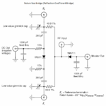
Hello, I have built and tested on the scope, the attached impedance bridge.
I would like to add an analogue (panel) meter to the DC-out and the Monitor-out ports, so that the instrument can be made portable.

I have a small 100uA meter which I could use. Also note that these ports output AC with a negative DC component on it.
Could I use this analogue uA meter to measure the DC and how should I connect it?
maybe I should use a voltmeter instead?
I am worrying about the measurements, I think these meters will ignore AC because they are slow and will display only the DC component of the AC waveform, is that right?
 

Attachments

  • schematic.PNG
    schematic.PNG
    34.3 KB · Views: 72

That circuit is well known and loved. The "monitor out" connection can usually be monitored by a multimeter, but can directly drive a analog uA meter. I simply used a DVM multimeter.

My choice would be to add a simple op-amp circuit. It does not have to be a very elaborate instrumentation type, though good low-cost op-amps are available. The first stage can be a buffer of gain=1, offering a high impedance to the monitor point. The next stage can supply some gain as needed to drive a meter, which then has a series resistor to make it a voltage measuring arrangement.

Since a bridge circuit is used to discover a null, you might use more op-amp for a non-linear limiter circuit, to have a high gain at the null, but be able to to handle off-balance situations without bending the meter needle. That way, you get a sensitive bridge that is also robust for overload.

Adding diodes with resistor ballast across the feedback gain-setting resistor of the gain op-amp might even make the whole thing possible with only 2 op-amps.
 
  • Like
Reactions: neazoi

    neazoi

    Points: 2
    Helpful Answer Positive Rating

Maybe, but the transformer is not broadband in the dc-ghz range. In fact I have built the bridge.
My implementation of the circuit is here **broken link removed** and I think it can go quite deep into the GHz region with the techniques used. I have only tested it on 10MHz, 50MHz, 144MHz and 430MHz currently.

- - - Updated - - -

That circuit is well known and loved. The "monitor out" connection can usually be monitored by a multimeter, but can directly drive a analog uA meter. I simply used a DVM multimeter.

My choice would be to add a simple op-amp circuit. It does not have to be a very elaborate instrumentation type, though good low-cost op-amps are available. The first stage can be a buffer of gain=1, offering a high impedance to the monitor point. The next stage can supply some gain as needed to drive a meter, which then has a series resistor to make it a voltage measuring arrangement.

Since a bridge circuit is used to discover a null, you might use more op-amp for a non-linear limiter circuit, to have a high gain at the null, but be able to to handle off-balance situations without bending the meter needle. That way, you get a sensitive bridge that is also robust for overload.

Adding diodes with resistor ballast across the feedback gain-setting resistor of the gain op-amp might even make the whole thing possible with only 2 op-amps.

I think I am going to use a simple uA meter since I like simpliciry and since you say this can be driven directly by the diode.

To make more precise measurements I would directly use the scope, as it is already high impedance (1Mohm) and I have found that the two circuit outputs do not affect each other or the measurements if connected to high impedance ports.
I was wondering if the analogue needle uA meter is a high impedance device (I guess not) or how could I use an opamp or something to make it a high impedance. Else, I am going to use a DVM
 

A uA meter will have many turns of very fine wire on it's deflection coil, and will have it own quite low coil resistance.
It will also have a value of current that will cause it to deflect to maximum, called the FSD (Full Scale Deflection).

To use it in current measure mode, you calculate the value of the shunt resistance placed in parallel with it, such that when the maximum current to be indicated is running, then the split share of that current going through the coil is the FSD uA for the meter.

To use it in voltage measure mode, then a resistor is put in series with the meter, such that the value of the resistor, plus the resistance of the coil will set the current to be FSD uA when the maximum voltage to be indicated is across the combination. This is the mode you would use for the bridge.

In practice, this is extremely quick and easy to do, and estimating suitable values only takes very few minutes with a calculator. Analog multimeters have their sensitivity expressed in "Ohms per Volt". Where a reasonably sensitive uA meter movement is used, a typical value would be 20,000 Ohms/Volt. So, for a 5V maximum range, the impedance seen by the monitor point is 100K Ohms. This is a high enough impedance not to load the circuit excessively, yet low enough to shunt out noise. DVM are 11 MegOhms constant, so are very high impedance.

For null indications, a DVM sucks (unless it has a psuedo-analog bar-graph display). A fast glance at any analog display is immensely informative (try a wrist watch!). Finding a null on a DVM is confusing. DVM displays are good when a stable settled reading can be taken with precision.
 
  • Like
Reactions: neazoi

    neazoi

    Points: 2
    Helpful Answer Positive Rating
I was wondering what will be the case if two RF signals are fed into the RF input of the bridge?
For example if the RF input to the bridge is a combo generator.
All RF harmonics will appear in the RF port.
How one frequency measurement affects the others?
 

Hello,
What is the impedance of the AD converter of the ATMEGA644 microcontroller? Is it high enough to be connected directly to this bridge?
 

ADC inputs can have variable input impedance depending on whether the sample-and-hold cap is connected to the pin or not.
Sometime is good to use an op amp to buffer the signal. The op amp would have the benefit of allowing you to filter out frequencies above Nyquist, which is also good practice in ADC design.


Status
Not open for further replies.

Part and Inventory Search

Welcome to EDABoard.com

Sponsor

Back
Top