abcd567
Newbie level 6
IMPROVING PERFORMANCE OF A COCO BY LOWERING IT's SWR/IMPEDANCE MATCHING
IMPROVING PERFORMANCE OF A COCO BY LOWERING IT's SWR/IMPEDANCE MATCHING
It is well known that a large number of DIY CoCo makers get frustrating results, and only a relatively small number get satisfactory or good results. Main reason is high impedance & resulting high SWR which causes the antenna to perform poorly even if it has a high Gain.
I have tried to find a method to ease out the SWR without using test instruments. I tested it and it gave me an improvement of about 25 to 35%., not optimal, but better than nothing.
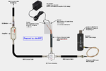
Please see sketches below showing an example of impedance matching using this method. It results in using a piece of coax between 0.75 to 0.9 of the length of halfwave elements of CoCo, and a 2.5 pF Capacitor in series. It is applicable to most CoCos without using test equipments. It requires trying four pieces of coax of lengths (0.75 x VF x 138 mm), (0.8 x VF x 138 mm), (0.85 x VF x 138 mm) and (0.9 x VF x 138 mm), and keep the one which give better results than others. The length of coax piece includes length of F-connector also.
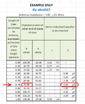
SKETCH 1 of 3 : IMPEDANCE TRANSFORMATION BY A PIECE OF COAX 0 to 1/2 WAVELENGTH LENGTH
SHETCH 2 of 3: IMPEDANCE MATCHING / SWR IMPROVEMENT METHOD

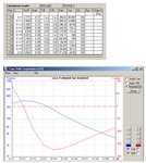
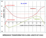
This method uses the fact that a piece of transmission line (Coax) transforms the impedance of antenna connected to it. The value of impedance seen at other end of coax depends on length of piece of coax. The impedance transforms in a cyclic manner, returnig back equal to antenna impedance every 1/2 wavelength. At a particular length in between 0 and 1/2 wavelength, the Resistance transforms to exactly the impedance of coax/receiver, and reactive component transforms from capacitive to inductive. At this point if a capacitor of appropriate value is inserted to cancel the inductive component to zero, only resistive component remains which is equal to system impedance, and stays same along remaining entire length of feed coax.
..
SHETCH 3 of 3: GRAPHICAL REPRESENTATION - IMPEDANCE TRANSFORMATION ALONG LENGTH OF COAX
IMPROVING PERFORMANCE OF A COCO BY LOWERING IT's SWR/IMPEDANCE MATCHING
It is well known that a large number of DIY CoCo makers get frustrating results, and only a relatively small number get satisfactory or good results. Main reason is high impedance & resulting high SWR which causes the antenna to perform poorly even if it has a high Gain.
I have tried to find a method to ease out the SWR without using test instruments. I tested it and it gave me an improvement of about 25 to 35%., not optimal, but better than nothing.
Please see sketches below showing an example of impedance matching using this method. It results in using a piece of coax between 0.75 to 0.9 of the length of halfwave elements of CoCo, and a 2.5 pF Capacitor in series. It is applicable to most CoCos without using test equipments. It requires trying four pieces of coax of lengths (0.75 x VF x 138 mm), (0.8 x VF x 138 mm), (0.85 x VF x 138 mm) and (0.9 x VF x 138 mm), and keep the one which give better results than others. The length of coax piece includes length of F-connector also.
SKETCH 1 of 3 : IMPEDANCE TRANSFORMATION BY A PIECE OF COAX 0 to 1/2 WAVELENGTH LENGTH

SHETCH 2 of 3: IMPEDANCE MATCHING / SWR IMPROVEMENT METHOD

This method uses the fact that a piece of transmission line (Coax) transforms the impedance of antenna connected to it. The value of impedance seen at other end of coax depends on length of piece of coax. The impedance transforms in a cyclic manner, returnig back equal to antenna impedance every 1/2 wavelength. At a particular length in between 0 and 1/2 wavelength, the Resistance transforms to exactly the impedance of coax/receiver, and reactive component transforms from capacitive to inductive. At this point if a capacitor of appropriate value is inserted to cancel the inductive component to zero, only resistive component remains which is equal to system impedance, and stays same along remaining entire length of feed coax.
..
SHETCH 3 of 3: GRAPHICAL REPRESENTATION - IMPEDANCE TRANSFORMATION ALONG LENGTH OF COAX

Last edited by a moderator:


