felixpius
Newbie level 1

- Joined
- Dec 4, 2014
- Messages
- 1
- Helped
- 0
- Reputation
- 0
- Reaction score
- 0
- Trophy points
- 1
- Activity points
- 14
I want to construct test bench for IGBT switching test.
I will model the igbt component using the measurement data on later.
It is my first trial to make PCB with components I buy.
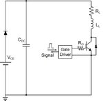
I think the basic schematic circuit is below.

Target IGBT model is IKP10N60T Infineon, which includes FWD.
( **broken link removed** )
For gate driver, 1EDI60I12AF Infineon.
It has isolation capability by itself.
( **broken link removed** )
The question is what type of input signal can be transmitted to gate driver.
Can signal generator directly apply signal input to driver or do i need another chip to control the driver?
And are there any other parts required to be added?
(eg. overcurrent protection, optocoupler for separating signal from power circuit, or output node for measurement)
Any tips will be helpful for me..
I will model the igbt component using the measurement data on later.
It is my first trial to make PCB with components I buy.
I think the basic schematic circuit is below.

Target IGBT model is IKP10N60T Infineon, which includes FWD.
( **broken link removed** )
For gate driver, 1EDI60I12AF Infineon.
It has isolation capability by itself.
( **broken link removed** )
The question is what type of input signal can be transmitted to gate driver.
Can signal generator directly apply signal input to driver or do i need another chip to control the driver?
And are there any other parts required to be added?
(eg. overcurrent protection, optocoupler for separating signal from power circuit, or output node for measurement)
Any tips will be helpful for me..
Last edited:
