Continue to Site

Welcome to EDAboard.com

Welcome to our site! EDAboard.com is an international Electronics Discussion Forum focused on EDA software, circuits, schematics, books, theory, papers, asic, pld, 8051, DSP, Network, RF, Analog Design, PCB, Service Manuals... and a whole lot more! To participate you need to register. Registration is free. Click here to register now.

IGBT Failure in BOOST Converter what may be the reasons?

Status
Not open for further replies.

rakesh1987

Junior Member level 3
Joined
Nov 17, 2011
Messages
29
Helped
0
Reputation
0
Reaction score
0
Trophy points
1,281
Activity points
1,478
Hello all,

my igbt connected to boost converter is failing , when operated at light load and 600v, its rated for 1200V and 40A, I am expecting a voltage spike at the IGBt causing its failure ? please help me to solve it?
 

Please.... some sort of circuit/ schematic/ explanation of how you have set it up, along with part numbers would be useful.

Otherwise all we can do is agree with your assessment.

cheers!
 

post your circuit along. else all we can do now will be based on assumption!:p
 

Post your schematic, along with voltage waveforms at gate and collector of the IGBT.

Does it instantaneously burn? Or does it run for some time? If so, how long?
You say it fails under light load. So, did you only use light load for testing? Did you test with higher power load? If so, what is the result?
 

please post circuit diagram. but still i think u are not releasing the energy of input winding completely during OFF time of IGBT eventually loading the IGBT with back EMF during ON time (depending on the topology u are using). this back EMF is further rides on the actual DC voltage which you are chopping. so, after few cycles, the accumulated voltage at the IGBT terminal reaches upto some critical level leading to burn it. i can give more explaination if u provide circuit and part number.
 

At the moment of switch-Off, the transistor is exposed to a jolt equal to A x V.

That means 600 V times whatever current it is carrying at the moment of switch-Off.

Suppose your supply is 12V, and your load is 3 mA at 600 V. This is 18 watts. The transistor may be carrying 2 A at switch-Off. In that case the jolt amounts to 1200 W.

The duty cycle is so short it can barely be measured. Nevertheless it occurs many times a second. The heating effect could be damaging, if allowed to build up. It would not matter what voltage and amps the device is rated to withstand.
 

we are also faced the same problem with IGBT, when designing a low power induction heating system.
at last we found the problem with zero voltage switching.
we found the problem only after analyzing the waveform using CRO.
 

Very high Voltage spikes occur during switch-off of current through an inductor. This voltage is potentially "Infinite", but of course always finds a way to discharge through SOME path at some value. In your case its probably the IGBT.....
The equations governing this are quite simple really --

During switch ON time, current builds in the inductor:

Ipeak = Vs . Ton / L
(assuming resistance in the charging path is negligible, and inductor does not go into saturation)
where Vs is supply voltage across inductor, Ton is the IGBT ON time period, and l is inductance.

This current CANNOT be stopped suddenly or changed discontinously, and the exact same equation is used during switch-off, except that Toff is much much smaller.
So now we get:

V = L . Ipeak / Toff
= L . Vs . Ton / L / Toff
= Vs . Ton / Toff

Toff is usually very small compared to Ton, hence the voltage can be seen to be huge !!

Ideally Toff should be zero ( or as small as possible in the uS region if not nS regions) to ensure that power losses in the IGBT are minimal.
However the smaller we make Toff, the larger is the kick-back voltage generated !!! This is why we ALWAYS connect a reversed diode across inductive loads - to dissipate safely the stored magnetic energy & prevent high kick-back volts.

The stored energy equation is : 1/2 . L . I^2
= (Vs.Ton)^2 / 2.L (in Joules)

Here notice that (counterintuitively), the energy is LARGER if inductance is smaller !!

cheers!

p.s. ppdr123 & BradtheRad ... you are both sorta correct, but not quite.
 

p.s. ppdr123 & BradtheRad ... you are both sorta correct, but not quite.

In reply, I would like to ask you some questions about items in your explanation:

Very high Voltage spikes occur during switch-off of current through an inductor. This voltage is potentially "Infinite", but of course always finds a way to discharge through SOME path at some value. In your case its probably the IGBT.....

Are you saying the coil cannot find a way to discharge through the capacitor? I ask this because it is typical to put a capacitor in the output stage of a boost converter. And a capacitor has very low resistance.

(I believe the coil can discharge through the capacitor.)

Toff is usually very small compared to Ton, hence the voltage can be seen to be huge !!

Is the voltage huge because (A) Toff is small, or is it (B) because the charged coil suddenly sees high resistance?

(I believe it is B, and this can bring on the (sometimes) sudden discharge at (sometimes) very high voltage.)

Ideally Toff should be zero ( or as small as possible in the uS region if not nS regions) to ensure that power losses in the IGBT are minimal.

When the charged coil sees low resistance, how does this affect the time it takes to fully discharge?

(I believe it lengthens the time in which it will discharge.)

However the smaller we make Toff, the larger is the kick-back voltage generated !!! This is why we ALWAYS connect a reversed diode across inductive loads - to dissipate safely the stored magnetic energy & prevent high kick-back volts.

In a boost converter, do we always connect a diode across the coil? Why or why not?

(I believe we omit the diode in a boost converter.)

- - - Updated - - -

-------------------------------------

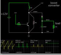
Here is a screenshot of my simulation of the situation described in the OP.


I made broad assumptions about component values and the supply voltage. Nevertheless the circuit action should be roughly similar.

The scope traces indicate how the central node (above the transistor) hits 600 V momentarily. This occurs as soon as the transistor shuts off.

Ideally the transistor shuts off instantly. However depending on how slowly it shuts off, the transistor could briefly carry several hundred watts of power.
 

Thanks all, iam attaching the circuit diagram Infenion IGBT is used , how to avoid the failure of IGBT?
 

Thanks all, iam attaching the circuit diagram...

Sorry, diagram not seen.

I always try to use the "Add an Image" button. It takes just a few steps to select an image from disk and upload. Copy the BBC code link (the very first one under the image) and paste it in my post.

It is awkward to use 'Manage Attachments.' Getting an image uploaded takes several steps. Often I take a wrong step.
 

...Are you saying the coil cannot find a way to discharge through the capacitor? I ask this because it is typical to put a capacitor in the output stage of a boost converter. And a capacitor has very low resistance.

(I believe the coil can discharge through the capacitor.)

yes of course it can, and will. I was writing about the case where only a switch & inductor are present. In a boost converter with the diode/cap, the voltage will rise until it is above Vdiode+Vcap, and then stay that way until discharged. Vcap will of course rise during this time.

Is the voltage huge because (A) Toff is small, or is it (B) because the charged coil suddenly sees high resistance?

(I believe it is B, and this can bring on the (sometimes) sudden discharge at (sometimes) very high voltage.)
these are sorta the same thing. i.e. Toff small <---> "sudden" off <---> "sudden" extremely high resistance
Oh yes - the discharge MUST take place somehow, through SOME route. Sometimes its through the air - if thats the earliest least resistance path it finds.

When the charged coil sees low resistance, how does this affect the time it takes to fully discharge?
(I believe it lengthens the time in which it will discharge.)

which low resistance do you mean ? if you mean when the diode forward conducts & charges the cap ?
Well, the cap voltage will rise as it charges ( as per C dee-V by dee-T equals I). This is not a "low resistance" as such, especially since current cannot change to infinity .... but rather is "controlled" by the inductor equation.

In a boost converter, do we always connect a diode across the coil? Why or why not?

(I believe we omit the diode in a boost converter.)

No diode of course. Once again, that point was only for general switch protection circuit which simply drives an inductor. For a boost converter there would probably be a way to control the PWM signal to the switch based on sensing of the output voltage.

- - - Updated - - -

-------------------------------------

Here is a screenshot of my simulation of the situation described in the OP.


I made broad assumptions about component values and the supply voltage. Nevertheless the circuit action should be roughly similar.

The scope traces indicate how the central node (above the transistor) hits 600 V momentarily. This occurs as soon as the transistor shuts off.

Ideally the transistor shuts off instantly. However depending on how slowly it shuts off, the transistor could briefly carry several hundred watts of power.

Nice simulations. I see similar traces on my real workbench oscilloscope.

In a practical setup, during startup you will notice that the spikes are flat-topped & wider at lower voltage (as the cap charges), and get narrower as the voltage increases. The "plateau" is where the inductor is dumping its energy into the cap.

A few questions of my own :)
1) how did you obtain ~600v specifically ? In simulation with ideal components, this should keep rising forever. In practical simulation/ workbench this will be limited by IGBT breakdown/ diode reverse voltage breakdown/ capacitor V rating. Also the inductor saturation current.
2) whats the purpose of the 20K resistor ?
3) you could try making the BJT switch off faster with a simple addition of a cap & resistor to its base input - to (1) help remove base charge, (2) ensure Vb goes to zero.

cheers!
 
Last edited:

It is awkward to use 'Manage Attachments.' Getting an image uploaded takes several steps. Often I take a wrong step.
The last step, in any case, should be to check if the image is shown in post, isn't it? It's somehow annoying that forum members need to guess about a possible circuit, detailed operation conditions and so on.
 

A few questions of my own :)
1) how did you obtain ~600v specifically ? In simulation with ideal components, this should keep rising forever. In practical simulation/ workbench this will be limited by IGBT breakdown/ diode reverse voltage breakdown/ capacitor V rating. Also the inductor saturation current.

Glad we've reached some kind of understanding.

In the simulation I attached a load which drew a few mA (I guessed because the OP says 'light load').

I played with its value, and the duty cycle, etc., until the output voltage was about 600 V.

With no load the output voltage will continue rising beyond all reason. If it is real hardware, some component would eventually break down.

2) whats the purpose of the 20K resistor ?

It's because the simulator sometimes displays oscillations during dead time. I believe it is tiny coil energy 'kicking' the diode open repeatedly each time the diode is full off.

By putting a resistor across the diode (or switching device), I find it eliminates the oscillations.

3) you could try making the BJT switch off faster with a simple addition of a cap & resistor to its base input - to (1) help remove base charge, (2) ensure Vb goes to zero.

This is worth a try. It may be a cure for the problem reported by rakesh1987 (the OP).

Since the simulator I am using does not model an IGBT, it might be helpful if you were to post a diagram showing recommended values.
 

I played with its value, and the duty cycle, etc., until the output voltage was about 600 V.

With no load the output voltage will continue rising beyond all reason. If it is real hardware, some component would eventually break down.
In other words, a boost converter must not be operated without controlling PWM in a closed loop. I would presume this as a trivial fact, but we didn't yet hear any details about the original problem.

Besides the possible problem of not limiting the boosted output voltage in the control circuit, I would expect too fast switching in combination with an unsuitable circuit layout as favourite cause for damaged IGBT.
 
  • Like
Reactions: tpetar

    tpetar

    Points: 2
    Helpful Answer Positive Rating
....I played with its value, and the duty cycle, etc., until the output voltage was about 600 V........

Fair enough.
Meanwhile, I was unable to reconcile/ match up some of your numbers --

For example, a peak current of 1.77A using 12v supply through a 1mH inductor requires an ON time of not more than 150uS. This corresponds to a freq of ~6.4KHz with a duty cycle of (say) 95% on.

Now this corresponds to an energy of ~1.56mJ per cycle, or a power of 1.56mJ x 6.4Khz = 10watts.
This 10 watts must be getting dissipated in the 120K load resistor, with some minor amounts in the diode/ 20K, for a steady state output voltage.

HOWEVER, a 10watt across 120k implies a voltage of 1095v !!! And not 605v as in your diagram.

Conversely, if the voltage IS steady at ~605v, then this is a power of ~3watts.
Once again, this implies a clock freq of around 1915Hz if the peak current of 1.77A is correct.

Some value someplace is incorrect.... but which is it ?

cheers!
 

Some value someplace is incorrect.... but which is it ?
The diode peak current should be 1.7 A. If it isn't, most of the coil energy must be lost elsewhere, preferably in the transistor due to slow switch-off.
 
  • Like
Reactions: tpetar

    tpetar

    Points: 2
    Helpful Answer Positive Rating
The diode peak current should be 1.7 A. If it isn't, most of the coil energy must be lost elsewhere, preferably in the transistor due to slow switch-off.

Thats not the answer I was looking for...
(Closing this thread now)
cheers!
 

No idea which answer you're looking for?

In fact it's just another viewpoint showing why the simulation results are inplausible.
 

No idea which answer you're looking for?

i tried to outline my calculations & the resulting inconsistency in #16

In fact it's just another viewpoint showing why the simulation results are inplausible.

imo simulations help tremendously in understanding & experimenting. Without the time/ tedium/ expense of real-world experiments. The final results are of course only proven by actual implementation & simulation and again experiment and .... the two go hand in hand.

i think your statement above is a bit implausible & sweeping. :-D

cheers!
 

Status
Not open for further replies.

Similar threads

Part and Inventory Search

Welcome to EDABoard.com

Sponsor

Back
Top