Continue to Site

Welcome to EDAboard.com

Welcome to our site! EDAboard.com is an international Electronics Discussion Forum focused on EDA software, circuits, schematics, books, theory, papers, asic, pld, 8051, DSP, Network, RF, Analog Design, PCB, Service Manuals... and a whole lot more! To participate you need to register. Registration is free. Click here to register now.

[SOLVED] IC 741 op-amp in open loop mode

Status
Not open for further replies.

paone

Newbie level 5
Newbie level 5
Joined
Jan 17, 2014
Messages
10
Helped
0
Reputation
0
Reaction score
0
Trophy points
1
Activity points
85
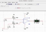
I have designed an open loop OP-AMP(IC741) circuit, for which i've provided 2 different input voltages and Resistance=1kohm. And given,Vdd=+10V and Vss=-10V (approx). I expected a saturated output of either +10 or -10V(nearly) , but interestingly i found the output less than 1V. Should i modify the circuit for saturated output ??
 

Post your circuit.
 

Maybe your input voltages are not within the input common mode voltage range. With your plus and minus 10V supply, the input voltages must be plus or minus 7V or less.
 

As there is little info in your post, following might be the reasons for not getting the expected results -
> Look for proper grounding of both +V and -V supplies as well as the input signals you are giving to the opamp
> Look at the waveform of the input signals if they are not DC - then see what you should be getting as output
> How you are measuring the output? CRO or DMM. CRO will be better as you will get all clarity about the signals
> If you are feeding a AC signal to the inputs and measuring output with DMM, then you may see wrong reading
> Probably use a load resistor of 10k in your measurements. (may not change much)
 

op amp 2.png.jpg

The result from software(MULTISIM) is completely different from the hardware.
 

The 1 k resistors are meaningless.

A similar output voltage can be expected in real hardware. If you don't get it, the OP is defective or you connected it wrong (different from the schematic).
 

1. circuit is properly grounded
2. i/p are in DC form
3. Using Multimeter( in DC mode)
4. i am not using any load resistance( since multimeter has enough resistance to find voltage)

Does IC 741 can be used in open loop mode or not ?( for saturation outputs )
If not, please suggest me an IC for comparison( I've two inputs "160mV" and "40mV" (approx., )
 

In our actual project, we have two input voltages ( 160mV and 40mV approx., ). So could u please specify the i/p resistance values, so that the output can be a saturated one.
 

741 can be used "in open loop mode" (as a comparator). The only requirement is a dual supply so that the input voltage is in common mode range. +/- 10 V should be fine. No input series resistors required.
 

In our actual project, we have two input voltages ( 160mV and 40mV approx., ). So could u please specify the i/p resistance values, so that the output can be a saturated one.

These voltages will not turn on the transistors in the opamp IC. You need higher voltages .. more than 700mV ideally.
 

These voltages will not turn on the transistors in the opamp IC. You need higher voltages .. more than 700mV ideally.
Sorry, that's completely wrong. Less than millivolts input are sufficient to drive the OP output into saturation, of course with sufficient supply voltages.
 
741 can be used "in open loop mode" (as a comparator). The only requirement is a dual supply so that the input voltage is in common mode range. +/- 10 V should be fine. No input series resistors required.

Thanx a lot. Circuit is working with no i/p resistances and got the expected saturated results.
one more problem is, "If both the i/p values are equal, then the o/p is -ve sat value instead of zero( 0V). What to do, to get o/p as zero volts ??"
 

Sorry, that's completely wrong. Less than millivolts input are sufficient to drive the OP output into saturation, of course with sufficient supply voltages.

My bad, I got confused with my earlier experience on other device and related to it. Thanks for correcting.
 

I got this info from a website......
" Many OP-AMP's have two pins labeled OFFSET NULL. When both inputs are connected to the same voltage, the output should be zero. If the project requires a zero output under these conditions, the OFFSET NULL should be adjusted by adding a 10k pot between the Offset Null pins with the centre of the pot connected to 0v. By adjusting the pot, the output will produce 0v. "

Does this make o/p to be zero(possibly) ??
 

If both the i/p values are equal, then the o/p is -ve sat value instead of zero( 0V). What to do, to get o/p as zero volts?
The output with zero inpiut is uncertain due to offset voltages. It's effectively impossible to achieve 0 V output in open loop, the OP gain is too high.

- - - Updated - - -

You can use the adjustment to cancel input offset, but it doesn't give you stable zero output. That's neither claimed in the quoted statement.
 

You posted the Multisim schematic that shows the inputs at +4V(non-inverting) and at +6V (inverting) and it correctly shows the output saturating at -9V with a fairly high current into its 1k ohm load.
Then why did you say you "found the output less than 1V"?

The lousy old (47 years old) 741 opamp is shown on its datasheet to have DC gain typically 200,000 times and might be higher (its minimum DC gain is 50,000). Then an input difference of only 45uV will cause the output to saturate when its supply is plus and minus 10V. But its input offset voltage is much higher with a maximum of 6mV.

Your info about offset null from a website is COMPLETELY WRONG! The datasheet for the 741 opamp shows the slider of the pot connected to the negative supply voltage, not ground.
 

1. The one that I've posted(image) is done in a Multisim software, where i can get the req. saturated values.
But later on I've found to get the same from hardware equipment. Thanx to FvM
2. From the datasheet i could not find out what to do with the OFFSET NULL pins to make my OUTPUT to be zero volts. That is why i got confused with that website.
3. Still trying to get a possible solution for getting zero output from the circt.
 

Status
Not open for further replies.

Part and Inventory Search

Welcome to EDABoard.com

Sponsor

Back
Top