Continue to Site

Welcome to EDAboard.com

Welcome to our site! EDAboard.com is an international Electronics Discussion Forum focused on EDA software, circuits, schematics, books, theory, papers, asic, pld, 8051, DSP, Network, RF, Analog Design, PCB, Service Manuals... and a whole lot more! To participate you need to register. Registration is free. Click here to register now.

I nees help about DC-AC Inverter

Status
Not open for further replies.

waldopulanco

Member level 1
Joined
Nov 6, 2013
Messages
40
Helped
0
Reputation
0
Reaction score
0
Trophy points
6
Activity points
296
I need help about DC-AC Inverter

2 years ago i have created a 150 watts DC-AC Inverter (12 VDC input and 220VAC Output) i was found the Schematic Diagram here **broken link removed**

then after i built, i test it and it was fine with the 80 watts bulb i try to bulb 100 watts but the light was dim!! then i try it to Flourecent with starter but the output voltage was drop to 50vac during the start, and i try it to colored tv 80 watts but after the click the power button the output voltage from in verter was drop to 50vac!!

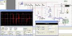
then i try it to simulate using Tina Design Suite and there is a problem to when i load a bulb of 100watts the output voltage was drop to 150vac!! but when i try to 50 watts bulb it was fine!!

here is the simulated diagram using Tina Design Suite!!
DC-AC_Inverter.JPG

help me to make it perfect!! because my inverter was never to use because of this problem!!

thanks!!!
 
Last edited:

The voltage measurements suggest that the major voltage drop is in the transformer, which can't be further commented without knowing the model parameters.

Without this problem, on-resistance of IRFP250 is already creating a noticeable voltage drop at higher load currents, so we can say that the inverter has a soft output characetristic by design.

thanks!! ok let me try the other IRFP!! thanks!!
 

The transformer problem hasn't been clarified. In your simulation, the transformer seems to cause most of the problems. This might happen in your real inverter too. Another point is battery and cable voltage drop. Did you check it?
 

The transformer problem hasn't been clarified. In your simulation, the transformer seems to cause most of the problems. This might happen in your real inverter too. Another point is battery and cable voltage drop. Did you check it?

yes i check the cable wire and the connection!! AND ITS FINE!! i think the problem is in the circuit!! thanks for the reply!!
 

The transformer problem hasn't been clarified. In your simulation, the transformer seems to cause most of the problems. This might happen in your real inverter too. Another point is battery and cable voltage drop. Did you check it?

the cable is #10 thick!! and the battery is 12 volt 48 ampere!! transformer is according to my calculation the wattage of transformer is 150watts to 200watts!! i think the problem is in the circuit!!!!
 

i replce the 12volt regulator with diode!! and its better than 12v regulator!!

here is the screenshoot:
98656d1384691672-inverter-harry.jpg


But i need to improve it!! i think the wave form is not a perfect!! hope you can help me!!

thanks a lot!!
 

Attachments

  • Inverter by harry.JPG
    Inverter by harry.JPG
    198.9 KB · Views: 114

Status
Not open for further replies.

Similar threads

Part and Inventory Search

Welcome to EDABoard.com

Sponsor

Back
Top