Continue to Site

Welcome to EDAboard.com

Welcome to our site! EDAboard.com is an international Electronics Discussion Forum focused on EDA software, circuits, schematics, books, theory, papers, asic, pld, 8051, DSP, Network, RF, Analog Design, PCB, Service Manuals... and a whole lot more! To participate you need to register. Registration is free. Click here to register now.

I need help to change the circuit with timer (HEF4013B Dual D-type flip-flop)

Status
Not open for further replies.

KamilCh

Newbie level 3
Joined
May 18, 2015
Messages
4
Helped
0
Reputation
0
Reaction score
0
Trophy points
1
Activity points
28
Hello,

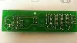
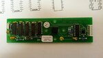
I have a mechanical shaker that works in duty 1min or 10min. I would like to work in continues way. Is it possible? I attached files from this shaker. How I can change the circuit? Thank you in advance for the help.

Fif1.jpgFig2.jpg
 

What is "continues way"? Do you mean that you want it to work continuously and never turn off?
If you post the schematic we can show you how to bypass the timer.
 

What is "continues way"? Do you mean that you want it to work continuously and never turn off?
If you post the schematic we can show you how to bypass the timer.

Yes, sorry for misunderstanding. I want to have always on and never off or at least if it is possible to increase sufficient long timer's time.

For the schematic...It is all magic here. I do not have it. We have just received this equipment from another lab without any documentation. I was trying to contact company to give my any clue or information but without response. This small circuit board is connected to another one where is a controller of the motor and power supply.

Therefore, I posted here that maybe somebody will be able to help me...
 

The second picture shows that the IC2 is a dual DFF which means the timer stuff must be the other ICs on the other end of the board, which I can't read the part numbers on at all.

You should trace out the signals, the boards looks like a 2 layer board so it should be pretty easy to create a schematic of the board.

Thanks for replay. I will try to do a schematic myself. Meantime I did I hopeFig3.jpgFig4.jpg better pictures. The second ICs is HEF4011BP. Please, look at the pictures.
 

I was trying to draw a schematic but it became messy. I put again two pictures from up view and underneath view. In addition, there are from left HEF4011B, then 3x CD4040B then HEF4012BE, switch and HEF4013B. Can you help me somehow without the schematic? Maybe if it is not possible to switch off it then maybe it is possible to increase time of working from 10 min to for example 1h?

Thank you in advance.
 

Attachments

  • Fig6.jpg
    Fig6.jpg
    1.3 MB · Views: 71
  • Fig5.jpg
    Fig5.jpg
    1.6 MB · Views: 58

Status
Not open for further replies.

Part and Inventory Search

Welcome to EDABoard.com

Sponsor

Back
Top