Continue to Site

Welcome to EDAboard.com

Welcome to our site! EDAboard.com is an international Electronics Discussion Forum focused on EDA software, circuits, schematics, books, theory, papers, asic, pld, 8051, DSP, Network, RF, Analog Design, PCB, Service Manuals... and a whole lot more! To participate you need to register. Registration is free. Click here to register now.

I need help selecting a logic level gate MOSFET

Status
Not open for further replies.

red913

Newbie level 5
Joined
Mar 28, 2013
Messages
9
Helped
0
Reputation
0
Reaction score
0
Trophy points
1,281
Activity points
1,370
Hello
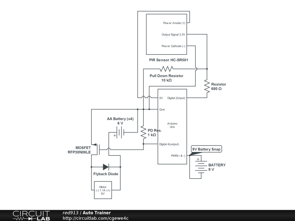
I'm fairly new to small electronics. I know the basics of ohms law and some other little things here and there about circuit basics. So I have drawn up this basic circuit and tried to provide all the info necessary to help me select the right mosfet for my application. My attempts at picking the right one have been frustrating at best as all the specs are a little confusing to me. Basically if the PIR senses movement, it'll send a signal to the Arduino, which then sends power to the mosfet to take power from a separate battery and finally activate the motor but only for a short moment and it should be fairly infrequent.

So what I've figured out so far is I need a logic gate mosfet, n-ch. Almost all will handle the 6V battery I've attached to it. But the other mosfet specs I get confused on. So if someone has a mosfet suggestion for my application I'd greatly appreciate it! :) ...and here is the circuit:
1024x768
 

1) You will want to put the FET in the Gnd lead of the motor if you can. As you have it drawn you are using "high side switching" which is difficult.
2) Once you move the FET a IRLD024 should work for you. IRLD024PBF-ND US$ 1.00 at Digi-Key.
 
  • Like
Reactions: red913

    red913

    Points: 2
    Helpful Answer Positive Rating
Motor rotation is important as it drives a pump. Positive on the motor needs positive from the source, otherwise it won't work the way I need it to. That is why I sent power from the mosfet (+) to (+) on the motor. So does it still works like it is then right?

- - - Updated - - -

1) You will want to put the FET in the Gnd lead of the motor if you can. As you have it drawn you are using "high side switching" which is difficult.
2) Once you move the FET a IRLD024 should work for you. IRLD024PBF-ND US$ 1.00 at Digi-Key.

One more thing. The Vgs(th) (Max) @ Id 2V @ 250µA... is that the max voltage I can run through the mosfet or the voltage needed to turn it "on"?
 

1) Can you connect the motor + to the battery +, the motor - to the FET Drain, and the FET Source to Gnd?

2) Vgs(th)(Max) is the maximum voltage required across the gate to source to make the FET start to turn on (threshold). The gate can take up to +/-10V without damage.
 
  • Like
Reactions: red913

    red913

    Points: 2
    Helpful Answer Positive Rating
Thank you so much Doug. You've been very helpful and I truly appreciate it. :)
I've made the changes you've suggested.(I think I got the mosfet symbol in the right orientation.)
Is that +/- 10V a general rule-of-thumb, or is it calculated somehow?Nevermind, I see it in the data sheet.
Also any suggestions on the flyback diode? Will this work?
1024x768
 
Last edited:

Actually you have the FET Source and Drain terminals reversed.
The flyback diode is recommended for any inductive load such as a motor. The current rating of the diode should match the current through the motor.
It would be better if you can run the battery negative to the FET pin instead of to the Uno pin. That keeps the heavy motor currents off of the Uno PCB and prevents small voltage losses in the Gnd wiring from affecting the FET Gate drive.
If this was a larger FET or you were using a very high PWM frequency you would want a FET driver chip between the Uno and the FET. But for this small a FET you should be fine.
"Standard" FETs usually take up to +/-20V on the gate. "Logic Level" FETs take less. Always check the data sheet to be sure.
 
  • Like
Reactions: red913

    red913

    Points: 2
    Helpful Answer Positive Rating
Actually you have the FET Source and Drain terminals reversed.
The flyback diode is recommended for any inductive load such as a motor. The current rating of the diode should match the current through the motor.
It would be better if you can run the battery negative to the FET pin instead of to the Uno pin. That keeps the heavy motor currents off of the Uno PCB and prevents small voltage losses in the Gnd wiring from affecting the FET Gate drive.
If this was a larger FET or you were using a very high PWM frequency you would want a FET driver chip between the Uno and the FET. But for this small a FET you should be fine.
"Standard" FETs usually take up to +/-20V on the gate. "Logic Level" FETs take less. Always check the data sheet to be sure.

Thank you, but the problem I'm running into is if I movie the battery (-) to the FET pin(gate pin?) that in turn removes the Arduino output pin which is supposed to trigger the rest of the circuit. So after that I don't know where else I would hook it up at. I understand you said it would be better, but perhaps in this circuit it's not possible. Also, I thought that the gate never saw the motor currents as they are running through the source drain circuit?
 

You have two choice , one is high side switch and the other low side switch.

For the high side switch it can be done with both a Nmos or Pmos but the Nmos is complicated so Pmos will be easier to use.
In this mode (with Pmos) you connect the source to the positive supply, the drain to the load (+ side) and the other side of the load to GND.
The mosfet turns on when the gate goes lower than the source voltage more than the Vgs threshold voltage (in practice you need an even lower voltage to reduce the Vds on resistance), it turns off when the gate has a voltage that equals or is very close to the source voltage.

For the low side switch you use a Nmosfet, source to the GND, drain to the load (- side) , the other side of the load to the positive supply.
In this mode the mosfet turns on when the gate goes higher than the source voltage as much as Vgs threshold or higher (again you need higher than the Vgs-th parameter to get a low source-drain on resistance) and off when the gate level is close to the source voltage which is grounded (so you need almost 0 to the gate)

The low side switch with the Nmosfet is easier to use because when the gate gets 0 (or close) then the mosfet is off and when the gate gets 3v3 or 5v (assuming a logic level mosfet) it turns on, this is true no matter how much supply you use for the load , it can be 10v or 20v but the on/off levels will be the same.

For the high side switch (using Pmos) things are reversed and usually it is more difficult, for example if you have 10v to the source then mosfet will turn off when the gate gets 10v (or so) and on when it gets 7v or lower (as an example of a mosfet that can turn on with 3v).
As you can see controlling this directly from a MCU pin in a problem because 0 or 5v to the gate will keep the mosfet on so basically you will need a level translator to drive it with an mcu.

Now in your specific circuit, you are using a Pmosfet with a source voltage of 6v , the mosget will turn off when the gate is 0 but when you apply 5v it may be still on (depends on the threshold) so it is kind of problematic.

If there is no specific reason to use a high side switch them maybe you should consider a low side switch that can be controlled easier.
 

I thought I was using N-ch mosfet? I just grabbed the n-ch mosfet symbol from the list on circuitsimulator.com. Also, I thought that on the n-ch mosfets the triangle base opens up towards the source. Also I'm a little confused but the n-ch mosfets with low side switch is easier, right? That's what I thought I had set up. The most recent pic I posted up should be what you suggested. So I think I'll go with that. Thanks everyone.
 

  • Like
Reactions: red913

    red913

    Points: 2
    Helpful Answer Positive Rating
Status
Not open for further replies.

Part and Inventory Search

Welcome to EDABoard.com

Sponsor

Back
Top