Revolutionist
Newbie level 2
Hello!
i need some help from u guys i want to make a small device for my home solar system which perform smart switching and load transfer between solar system, battery bank and utility supply (AC supply 220V). System components : Solar Panels > Charge controller> Batteries>UPS
i wanna make a device which is connected after charger controller in sequence shown above and perform monitoring and switching tasks.
Well i have a rough algorithm about for working of this device which is as follows:
1-At DAY Time:
CASE I-When solar panels are generating enough power to support the load, UPS goes on inverting mode and start fetching power to load from solar panels (Utility and batteries stay idle in this condition).
CASE II- When solar panels are generating more power than required by load then excessive power will be transferred to to batteries to charge them.
CASE III- If weather is cloudy or Panels dont generate enough power then load will be transferred to utility supply and power generated by panels will b transferred towards batteries.
CASE IV- if Case III happens and utility is also not available then load will fetch the power from batteries (UPS will work in inverter mode)
2- Night Time CASE-I utility is available and load will fetch the power from utility
CASE-II utility is not available and load will fetch the power from batteries (UPS will work in inverter mode)
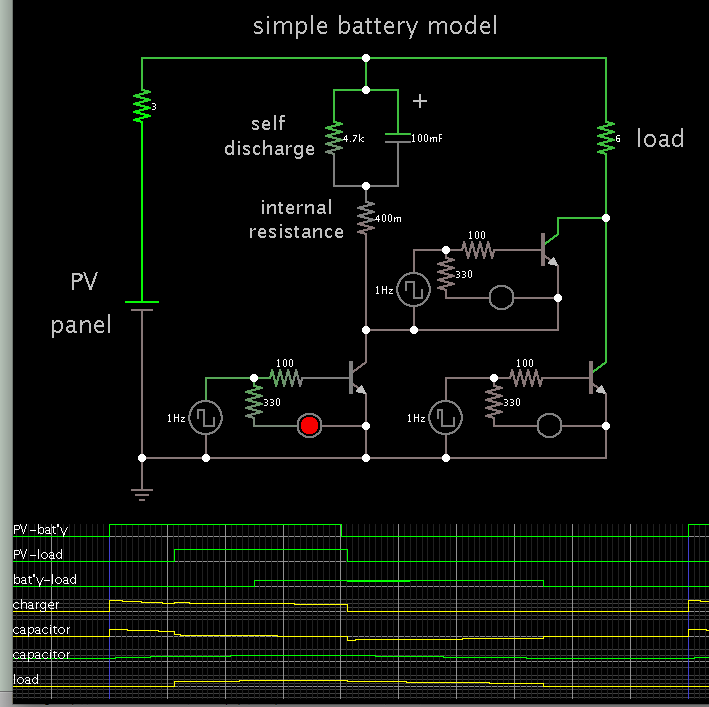
Simple schematics of device is attached with the thread
i need some help from u guys i want to make a small device for my home solar system which perform smart switching and load transfer between solar system, battery bank and utility supply (AC supply 220V). System components : Solar Panels > Charge controller> Batteries>UPS
i wanna make a device which is connected after charger controller in sequence shown above and perform monitoring and switching tasks.
Well i have a rough algorithm about for working of this device which is as follows:
1-At DAY Time:
CASE I-When solar panels are generating enough power to support the load, UPS goes on inverting mode and start fetching power to load from solar panels (Utility and batteries stay idle in this condition).
CASE II- When solar panels are generating more power than required by load then excessive power will be transferred to to batteries to charge them.
CASE III- If weather is cloudy or Panels dont generate enough power then load will be transferred to utility supply and power generated by panels will b transferred towards batteries.
CASE IV- if Case III happens and utility is also not available then load will fetch the power from batteries (UPS will work in inverter mode)
2- Night Time CASE-I utility is available and load will fetch the power from utility
CASE-II utility is not available and load will fetch the power from batteries (UPS will work in inverter mode)
Simple schematics of device is attached with the thread