Continue to Site

Welcome to EDAboard.com

Welcome to our site! EDAboard.com is an international Electronics Discussion Forum focused on EDA software, circuits, schematics, books, theory, papers, asic, pld, 8051, DSP, Network, RF, Analog Design, PCB, Service Manuals... and a whole lot more! To participate you need to register. Registration is free. Click here to register now.

howto operate a 12 volt dc RELAY with 89C51

Status
Not open for further replies.

Zohaibmaroof

Member level 2
Joined
Oct 10, 2010
Messages
50
Helped
1
Reputation
2
Reaction score
1
Trophy points
1,288
Activity points
1,832
i want to operate 12 volt relay with 89C51 any idea?
i wrote a program which set HIGH at pin 1.0 , although its working and giving 5 volt but does not turn on 6 volt relay
any idea what to do with this, i have also tried to connect a 2N2222 and also d313 with this pin 1.0 and take output from transistor's emitter pin making collector common but still it dose not work ,any additional circuitry i should made?

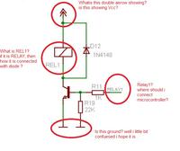
A 6VDC relay consume a minimum of 10 to 20 mA upon 5VDC, which is not possible to switch on directly from a microcontroller,

You need to use two resistors, one any NPN transistor and one diode (1N4148, 1N4001 to 1N4007)


This circuit will works for you for voltage from 5V to 24V, you may use 6VDC relay from 5VDC supply here, or you may use 12VDC relay with 12VDC supply
 

Thanks a lot for your reply but i have number of question which is shown in this picture i am putting below


the doublee arrow head is VCC
The RL is relay. the diode is a free wheeling diode (to suppress the inductive back EMF)
Relay 1 should connect to your microcontroller port

the last line was Ground Lines

---------- Post added at 06:27 ---------- Previous post was at 06:25 ----------

the doublee arrow head is VCC
The RL is relay. the diode is a free wheeling diode (to suppress the inductive back EMF)
Relay 1 should connect to your microcontroller port

the last line was Ground Lines
 

during my university level project i perform many experiments on Transistors. with all transistors c828, d313, etc whenever i connected the load to the emitter and ground and whatever vcc>=5V is applied at the collector pin; every time i got only 5V on emitter... :-( so when you connect the load to emitter of the transistor and apply any voltage at the collector up to 30v or more and try to switch the load then what you will get is all against your expectations :-( for any voltage at collector you will get only 5V at the emitter. and these 5V will never ever able to drive more than 5V loads. so always connect your load to the collector of the transistor and apply vcc to the collector of the transistor through load. and just directly ground the Emitter and drive the base of the transistor by the signal of the controller also put a resistor of 1K ohms between the base of the transistor and controller pin. and then i BET ..... it will 100% successfully drive your load. just follow the schemetic of MR masterleous.

Best regards

---------- Post added at 11:14 ---------- Previous post was at 11:14 ----------

during my university level project i perform many experiments on Transistors. with all transistors c828, d313, etc whenever i connected the load to the emitter and ground and whatever vcc>=5V is applied at the collector pin; every time i got only 5V on emitter... :-( so when you connect the load to emitter of the transistor and apply any voltage at the collector up to 30v or more and try to switch the load then what you will get is all against your expectations :-( for any voltage at collector you will get only 5V at the emitter. and these 5V will never ever able to drive more than 5V loads. so always connect your load to the collector of the transistor and apply vcc to the collector of the transistor through load. and just directly ground the Emitter and drive the base of the transistor by the signal of the controller also put a resistor of 1K ohms between the base of the transistor and controller pin. and then i BET ..... it will 100% successfully drive your load. just follow the schemetic of MR masterleous.

Best regards
 

no that circuit is not working
i have tried it , but when i connect that part which should be connected through microcontroller port , to VCC then relay turn on, but by microcontroller port it is not working

you know i lost 3 controller for this

---------- Post added at 13:15 ---------- Previous post was at 13:04 ----------

and can u tell me how can i charge 2 9 volt batterys which are connected in series like in this picture, i dont want to use any DPDT SPDT dpST SPST switch to use, i want that when i connect a 9 volt charger to the circuit or batterys it starts charging both of batterys simultaneously and also gives a beep that batterys are charging, yes i would use 8951 if it is required

Image0287[1].jpg
 
Last edited:

no that circuit is not working
you know i lost 3 controller for this

I couldn't see how your controllers were fried :???:
The only way to destroy a pin in the 89C51 family is to connect it to Vcc without a resistor (I suggest not to let it be less than than 1K). But the pin won't be harmed if connected directly to ground (not in case of the PIC MCUs when a pin is configured as output).

But you are right, the circuit shown doesn't work because this MCU (unlike the PICs) has I/O pins having an open collector (and likely just an internal weak pull-up resistance).

To give you the proper solution, I wish to know, in the least, the coil resistance of your 12V relay.

Kerim

Added (important):
Even by adding a resistor (called usually a pull-up resistor) between the pin and Vcc, Vcc should not be greater than the MCU supply voltage (likely 5V).
 
Last edited:

Based on the circuit already given, the following changes are needed:

R19 (22K), it could be removed (but it can be kept though).

R11 (1K), its value will be 3K9 and its terminal labelled "RELAY1" will be connected to 5V (the MCU supply).

NPN transistor (2N2222), its base will be connected to the MCU pin that will control the relay. (Note that R11 and R19 are also connected to the transistor base).

Option: For faster relay turn off, you may like to add a resistor in series with the diode D12 and having a resistance equal to to the coil resistance. The nearest standard value is 390R. The drawback of this addition is that the voltage rise at the transistor collector will be doubled (from almost 12V to 24V). But 24V is still a low voltage for 2N2222 therefore it is okay here.

Kerim
 

show me your schemetic.

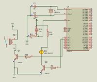
i just make this ckt and it worked pretty fine. i have used the same 89c51 controller.


you just have to use a seprate 12v supply for relay. and it will definitely switch.

here is the code:

org 00h

mov a,#11111111b

again:
mov p1,a

call delay
cpl a
sjmp again


delay:
mov r7,#10
b1: mov r6,#249
a1: mov r5,#200


djnz r5,$
djnz r6, a1
djnz r7,b1

ret

end

for the batteries you have shown in figure a dry batteries and are not rechargable. for charging battries first you have to know abut its chemistry that either it is lead acid type, NiMH, OR NiCd type cells. and then you can develop a charger for it.
look out here:
Battery Charger Circuits | CircuitDiagram.Org
 

Hi Qaisar,

On your circuit, it seems the weak pull-up resistance of P1 happened to be enough for your relay. R3 has no function here and it can be removed. I think the pin output current is around 50uA and assuming 2N2222 collector is at 2V hence its gain could be about 300 then Ic = 0.05 * 300 = 15mA. So if your coil relay resistance is about 10V/0.015 = 666 Ohms, it can be turned on.
In my work, I have to activate relays that may need around 100mA instead and I also prefer the driver transistor be saturated so that full 12V is applied on the relay.

Anyway, the idea here is to know how things work then it is up to each person deciding what is best for him :)

Kerim
 
Last edited:

show me your schemetic.

i just make this ckt and it worked pretty fine. i have used the same 89c51 controller.


you just have to use a seprate 12v supply for relay. and it will definitely switch.

here is the code:

org 00h

mov a,#11111111b

again:
mov p1,a

call delay
cpl a
sjmp again


delay:
mov r7,#10
b1: mov r6,#249
a1: mov r5,#200


djnz r5,$
djnz r6, a1
djnz r7,b1

ret

end

for the batteries you have shown in figure a dry batteries and are not rechargable. for charging battries first you have to know abut its chemistry that either it is lead acid type, NiMH, OR NiCd type cells. and then you can develop a charger for it.
look out here:
Battery Charger Circuits | CircuitDiagram.Org


no no... that picture which showing two 9v batterys are not rechargable battery , i just showed you the picture that i have connected batterys in this way,

and 1 thing more i will not make any charging circuit, i will simply connect a 9V DC charger/adapter to 9V Rechargable batterys, this procedure will reduce any extra circuitry , but stilll problem is how can i charg tw9 9V batterys connected in series so

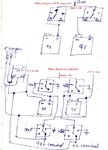
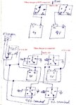
i have design a circuit for that ,well actually there are only relays... in this circuit can you check it and tell me is it correct circuit i design?


scan0006.jpg
 

this is my circuit which will connect batterys in series when charger/adapter is not connected and when charger/adapter is connected it will make parallel both batterys and obviously charger both of them by charger connected

scan0006.jpg
 

I don't use paralleling two voltage sources as batteries unless one is sure that they are identical (having the same open circuit voltage and the same internal resistance) and stay be so all the time.

It is better to charge them in series or each has its separate charger.

But no one will die if you charge them in parallel :)
 

i m not getting your point

how can i charge both batterys in series, i mean is it possible that if i connect negative terminal of charger/adapter to the negative terminal of 1st battery which is used to give negative 9 volt , and then connect positive terminal of charger/adapter to the positive terminal of 2nd battery?

are sure this will work , of it is then thats awesome, because it will reduce 2 relays in my circuit

But tell me is there any problem in my circuit which i have design?

---------- Post added at 19:26 ---------- Previous post was at 18:40 ----------

i think your circuit is to complicated also i m little bit confused of your program

well i have design a simple program and also i no need to make a huge circuitry for that, only 8951 and buzzer

here is the program

org 0000h
;;***********************************************************************************************************;;
;Charger Attach monitoring;
;;***********************************************************************************************************;;
MOV P3,#0FFH ;make p3 input port for checking charger connection LOW (ground)
MOV R7,P3 ;Transfer port 3 data to R7
CJNE R7,#01111111B,MOVE_ON ;if p3.7 gets LOW (which i will connect with charger negative terminal) then beep buzer
SETB p2.6 ;beep buzzer for 1 sec
mov r0,#255 ; Approx 1 sec delay
tt1:mov r1,#255
t2: mov r2,#12
t3: djnz r2,t3
djnz r1,t2
djnz r0,tt1
MOVE_ON:
CLR p2.6
sjmp $ ;program ends here if charger is reconnected then program will again beep buzzer
end
 

Hi Zohaibmaroof,

Try to follow one very specific rule,

Before testing any interface with your microcontroller, try your best to test with without microcontroller first, to avoid unnecessary burnout of your precious microcontroller. Confused?

a Microcontroller gives 5V output but current is minimum, Use a simple push button first instead of a microcontroller pin to test the circuit, so try the above circuits to operate a relay by simulating with a push button or a simple wire. be very careful to select a transistor for switching relay, for 12VDC relay 2N2222, BC547, 2SC828, 2SC945 transistors are perfect.

First thing is to select and use a perfect hardware for your project than use your time to program your microcontroller for your required function.

If you get success from push button simulation than it will also work with your microcontroller.
 
  • Like
Reactions: KerimF

    KerimF

    Points: 2
    Helpful Answer Positive Rating
this is my circuit which will connect batterys in series when charger/adapter is not connected and when charger/adapter is connected it will make parallel both batterys and obviously charger both of them by charger connected

View attachment 66307

I appritiate your struggle that you did to make the logic using relays, but since many ics and transistor are availble to make many times better charging circuits then relays. I think you want a back up source as well as to charge your batteries. its good but you have to know a few points regarding power sources and charging concepts.

1) for the adoptor out put, suppose you are using 9v adopter, and if its output is marked + and - on jack then it does not mean that it will provide you +9v and -9v...... with positive it means it will give u +9v and with - it means the ground point or 0v. the same condition is with the cell; a 9v cell with positive and negative marks on it will give you +9v and 0v(- terminal) or -9v and 0v( if you are considering + terminal as ground). the same concepts is applied on adopters.

2) for chargers: as i told you in my previous posts that you should know the chemistry of the battery first. however, for instance, for a lead acid battery, if you want to charge a 12v battery you should have to provide at least 14v at its terminals because on full charge its voltages rises up to 13.4v. similarly for a 24v lead acid battery you should keep the out put to 28v to fully charge the battries, and they will fully charge up to 26.8v or 27v.

now each battery consist of a number of cells. a 12v battery may consist of 6 cells, and each cell have 2v on it normally. and a fully charge battery have 2.23v per cell. thus a 18v lead acid battery(two 9v battries in series and having 9 cells in both, suppose, if available) on full charge should provide 2.23*9=20.0997v so your charger should provide a minimum of 21v at its out put to charge the batteries.

thus a good solution to charge an 18v battery is by using a voltage regulator IC LM317t by fixing its output to 21v. you have to study and learn about using the circuit of lm317 as a charger. just look it out here.

Battery charger circuit using LM317. - Electronic Circuits and Diagram-Electronics Projects and Design

Lead Acid Battery Charger Circuit

**broken link removed**

**broken link removed**

these will give you a wide concept about charging a battery.
 

I want to thanks to all those people who answered my Question

Here is my FINAL YEAR Project's video which i have finally completed with best excellence .watch it out

Ultrasonic navigation System first time made in Pakistan if i am not Wrong(Made By Zohaib) - YouTube

---------- Post added at 01:56 ---------- Previous post was at 01:54 ----------

Hi Zohaibmaroof,

Try to follow one very specific rule,

Before testing any interface with your microcontroller, try your best to test with without microcontroller first, to avoid unnecessary burnout of your precious microcontroller. Confused?

a Microcontroller gives 5V output but current is minimum, Use a simple push button first instead of a microcontroller pin to test the circuit, so try the above circuits to operate a relay by simulating with a push button or a simple wire. be very careful to select a transistor for switching relay, for 12VDC relay 2N2222, BC547, 2SC828, 2SC945 transistors are perfect.

First thing is to select and use a perfect hardware for your project than use your time to program your microcontroller for your required function.

If you get success from push button simulation than it will also work with your microcontroller.

I want to thanks to all those people who answered my Question

Here is my FINAL YEAR Project's video which i have finally completed with best excellence .watch it out

Ultrasonic navigation System first time made in Pakistan if i am not Wrong(Made By Zohaib) - YouTube

---------- Post added at 01:58 ---------- Previous post was at 01:56 ----------

Hi Zohaibmaroof,

Try to follow one very specific rule,

Before testing any interface with your microcontroller, try your best to test with without microcontroller first, to avoid unnecessary burnout of your precious microcontroller. Confused?

a Microcontroller gives 5V output but current is minimum, Use a simple push button first instead of a microcontroller pin to test the circuit, so try the above circuits to operate a relay by simulating with a push button or a simple wire. be very careful to select a transistor for switching relay, for 12VDC relay 2N2222, BC547, 2SC828, 2SC945 transistors are perfect.

First thing is to select and use a perfect hardware for your project than use your time to program your microcontroller for your required function.

If you get success from push button simulation than it will also work with your microcontroller.

I want to thanks to all those people who answered my Question

Here is my FINAL YEAR Project's video which i have finally completed with best excellence .watch it out

Ultrasonic navigation System first time made in Pakistan if i am not Wrong(Made By Zohaib) - YouTube
 

Status
Not open for further replies.

Part and Inventory Search

Welcome to EDABoard.com

Sponsor

Back
Top