Continue to Site
Follow along with the video below to see how to install our site as a web app on your home screen.
Note: This feature may not be available in some browsers.
Hello KlausHi,
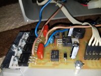
I agree, it seems to be a series connection of a zener with a standard Si diode.
Without knowing any information about the circuit it is absolutely impossible for us to give any zener voltage recommendation.
So it's on you to provide informations about the device, the PCB, the function, the circuit...
Klaus
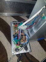
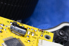
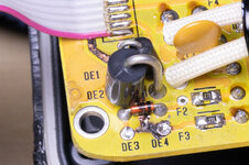
Hi There are no Z anywhere on board. there are two other diodes DE5 and DE6 both with C5 labled on them.Your photo shows DE3 DE4. Evidently labelling two diodes. A zener diode often has a label containing the letter Z.
D can label a zener (because it's a diode) although we'd like to find out what convention is used on your board. Look around the board for a label Z or ZD, near a component that appears to be a zener diode. If you find one then it suggests your cracked diode is a plain type.
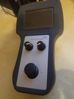
The circuit that goes the cracked diode goes to pin 2 which is a direction Signal with 0V-5V Voltage
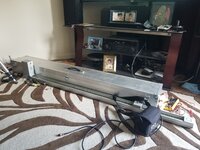
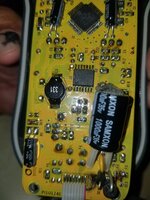
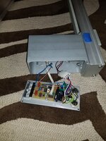
Hi Yes on the slider where all connections are made, Power, controller there is another PCB with an L7812CV G408CV6 CHN 106On the assumption it's a zener diode, its purpose could be to limit voltage to the device which we assume runs on 5V.
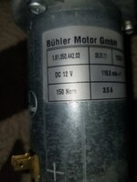
Your board power supply is 12V. Do you see voltage regulator IC's? For 12V?
5V, example, 7805?
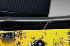
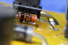
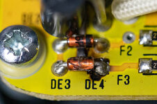
The cable pulled away from connector, or it could of been me sliding the unit back and forth trying to calibrate it. i tried to desolder that outer DE3, DE4 diode and it just fell apart.Hi,
I see there is a copper trace burnt away.
Now i want to ask:
What was the reason for this huge damage? Did it come without any reason?
Klaus
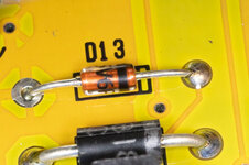
Im been trying to identify this diode. the identifiers are C5V6P but i cant find them anywhere i think there is 1 more number or letter without removing.The cable pulled away from connector, or it could of been me sliding the unit back and forth trying to calibrate it. i tried to desolder that outer DE3, DE4 diode and it just fell apart.
Do you think i could fry the board ifHi,
It could be a BZX79C5V6 ..
Klaus
Hi any clue what the P would mean? Even if i take it out, and got the last letter or number i still wouldnt be able to find it? ...right? i live in San Diego Ca. I dont even know who to call.Hi,
It could be a BZX79C5V6 ..
Klaus
Any small (400 mW or so) 5.6V Z-diode will fit.
Be aware that Z-diodes are rugged components and don't fail without a reason, e.g. external overvoltage or short circuit. Other components may have been damaged by the respective event, too.
Hi Dick_Freebird take a look By the way ThanksIs there an un-fried board on which you could measure forward and reverse voltage?
I am still in lined to think the diode might be a plain PN if the intact one is the zener. But in series @ over current the zener would see 8x the Pdiss and fail first, die size and thermals being equal.
Stand that on its head for gross reverse voltage on the stack with a "good ol' 1N914" breaking over at 50V give or take and the zener then being forward and barely warm.