Continue to Site

Welcome to EDAboard.com

Welcome to our site! EDAboard.com is an international Electronics Discussion Forum focused on EDA software, circuits, schematics, books, theory, papers, asic, pld, 8051, DSP, Network, RF, Analog Design, PCB, Service Manuals... and a whole lot more! To participate you need to register. Registration is free. Click here to register now.

How to using apply mosfet for Battery to Battery Charging cicuite

Status
Not open for further replies.

bkar

Junior Member level 3
Joined
Nov 1, 2010
Messages
26
Helped
1
Reputation
2
Reaction score
1
Trophy points
1,283
Visit site
Activity points
1,626
mosfet.png
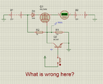
Why this is not work?
 

hi
Measure the Vgs voltage, is the MOSFET getting the correct Vgs for Drain/Source conduction.??

E
 
  • Like
Reactions: bkar

    bkar

    Points: 2
    Helpful Answer Positive Rating
Hi,

the fet switches ON when gate voltage is about 4V (look at datasheet for exact value) above source voltage.

Source voltage is 12V (battery)
So you need 16V at gate.

But it is about 10V when button is not pressed and about 0V when button is pressed.

Never above 16V. --> No current.
******************
If you don´t use R1 then voltage is about 20V when button is not pressed and 0V when button is pressed.
So current will fow when button is not pressed.

*********
Use a P-Ch FET and exchange source and drain. but don´t forget to limit gate-source voltage. ...Ah i just saw that here R1 is usefull, it limits gate source to about 10V.


Klaus

Dear Klaus,

Actually I am little weak in calculation. You said only R1 is useful. Should I remove other resistor from the circuit? And I wanted to use the schematic in a charge controller and the condition is when gate pulse is 0V current pass through Battery B1 to Battery B2 And when gate pulse is 5V current is not able to pass through B1 to B2. Please check th picture.Is this OK?mosfet2.png

Thanks in advance
bkar
 

Hi,

have you recognized the change in current reading? Now it´s not "0.00" anymore. Instead it is nothing. In my eyes this must be the overflow sign.

You don´t have any current limiting device in your circuit. In reality this may cause overheat and fire.

If you want to limit to 100mA you need a resistor. (put in your desired current in the calculations below)

20V = Supply, 0.7V = diode voltage drop, 12V = battery voltage, 0.1V = FET voltage drop (allvalues are estimated, the simulator is more precise than me)
R = U/ I; U = 20V - 0.7V -12V - 0.1V = 7.2V

R = 7.2V/0.1A = 72 Ohms. Power = U x I = 0.1A x 7.2V = 0.72W

Klaus
 
  • Like
Reactions: bkar

    bkar

    Points: 2
    Helpful Answer Positive Rating
Status
Not open for further replies.

Part and Inventory Search

Welcome to EDABoard.com

Sponsor

Back
Top