Welcome to our site! EDAboard.com is an international Electronics Discussion Forum focused on EDA software, circuits, schematics, books, theory, papers, asic, pld, 8051, DSP, Network, RF, Analog Design, PCB, Service Manuals... and a whole lot more! To participate you need to register. Registration is free. Click here to register now.
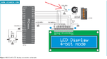
Hi, I want to use a fixed contrast (sorry for a mistake in a title) on 2x16 charachter LCD display, but don't know how to connect properly and how to get the correct value for the resistor.
Using the potentiometer, change the resistance until the contrast is what you want. Then turn the power off and connect a multimeter to calculate the resistance for your selected contrast. Place on probe on the pin connected to Vcc, the other to the middle pin. Or you can place one probe on the middle pin and the other on the pin connected to ground and subtract from 10K ohms. If you want to replace simply replace the potentiometer with the same value of resistance (or closest value to it). One pin of the resistor connects to Vcc the other to the input of your LCD.
Using the potentiometer, change the resistance until the contrast is what you want. Then turn the power off and connect a multimeter to calculate the resistance for your selected contrast. Place on probe on the pin connected to Vcc, the other to the middle pin. Or you can place one probe on the middle pin and the other on the pin connected to ground and subtract from 10K ohms. If you want to replace simply replace the potentiometer with the same value of resistance (or closest value to it). One pin of the resistor connects to Vcc the other to the input of your LCD.
Thank you Chops211.
Can I also ask another thing here, so I won't need to open another topic?
I am making a simple unit based on PIC MCU that will control solar water heater unit.
The question is:
Do all thermistors have linear relation between temperature and its resistance - can I get the relation koeficient with measuring resistance at two know temperatures?
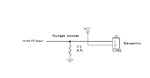
Can I connect thermistor directly to the PIC port pin like attached diagram shows.
In contrast to resistance thermometer, that has a fairly linear characteristic, all thermistors have rather non-linear behaviour. In a small temperature range, a linear approximation may be sufficient exact anyway. See a brief overview of expectable characteristics: Thermistor - Wikipedia, the free encyclopedia
With a microprocessor, it's generally easy to use either an exact mathematic function or an empirical lock-up table for the thermistor characteristic.
The suggested voltage divider circuit is fine, of course the fixed resistor should be selected according to the thermistor data to achieve best resolution.
Problem is that I don't know what kind of thermistors are allready integrated into a hot-water boiler and I can't change them. If I could I will most surely use digital temp sensor.
I have read about temp sensors (thermocouples, RTDs and thermistors) on wikipedia, but I didn't found thing about nonlinearity for thermistors. At contraray author indicated:
Assuming, as a first-order approximation, that the relationship between resistance and temperature is linear, then:
where
ΔR = change in resistance
ΔT = change in temperature
k = first-order temperature coefficient of resistance
Furthermore it's discussing thermistor non-linearity explicitely by suggesting different characteristic equations for resistance versus temperature. But it doesn't tell about the parameter range found with common thermistors. They can be found more clearly in manufacturer datasheets.
If you are able to determine the resistance of your thermistor for two known temperatures, you should be able to find the best characteristic curve from a selection of typical thermistors from manufacturer specifications. See below document.
This site uses cookies to help personalise content, tailor your experience and to keep you logged in if you register.
By continuing to use this site, you are consenting to our use of cookies.