Continue to Site

Welcome to EDAboard.com

Welcome to our site! EDAboard.com is an international Electronics Discussion Forum focused on EDA software, circuits, schematics, books, theory, papers, asic, pld, 8051, DSP, Network, RF, Analog Design, PCB, Service Manuals... and a whole lot more! To participate you need to register. Registration is free. Click here to register now.

how to transform a common anode display to common cathode?

Status
Not open for further replies.
Hi;
You must invert all drivers:
- for the commons change Q2...Q5 to NPN
- invert the segment-side HC4094 outputs

If you have the source and you can modify and recompile it, no more phisical part needed (except the 4 pcs of basic resistors for the new NPN common drivers) because all signal inverting may be done via software, otherwise use 4 inverter-buffers for drive the transistor basics and one for invert the HC4094 input data (pin2).
The emitters of the new NPN common driver transistors are bundled to GND.
 

The project is here http://elm-chan.org/works/cmc/report.html and the source is at the end of this page. The code is relatively small. Would somebody spend some time to do it for me?
I could donate a small amount for doing it even...
 

Hi;
I checked the source text. Unfortunately, written in assembly language, is not sufficiently commented, so it is very difficult to modify it, at least for me, who is not really familiar with this processor :) .
I propose the hardware solution: only one 14pin Hex Inverter (eg 74HC04) to be added.
 

maybe a similar chip like the 74hc4094 exists that has inverted outputs???
 

maybe a similar chip like the 74hc4094 exists that has inverted outputs???

No, the HC4094 outputs are not need to be inverted, only its data input (pin2) as I wrote above.
To do this use one of the 6 inverters in the HC04 (and other 4 inverters to driving the 4 NPN transistor basics).
 

I am sorry to bring back this old topic, but I was thinking that I could use an inverter like this one **broken link removed** without using another chip
 
Last edited:

I was thinking that I could use an inverter like this one **broken link removed** without using another chip

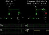
That schematic will work to invert a signal... but it will not invert current to a load.

As shown in this screenshot:


To use the above inverter, you would need to add another transistor stage. Your circuit board will be cluttered.

-----------------------------------------

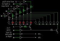
A couple of hex inverter chips (4049 or 4069) would allow you to use your led display, with less clutter:

 
  • Like
Reactions: neazoi

    neazoi

    Points: 2
    Helpful Answer Positive Rating
It's easier to get proper 7-seg display than making conversions.
 
  • Like
Reactions: FvM

    FvM

    Points: 2
    Helpful Answer Positive Rating
It's easier to get proper 7-seg display than making conversions.

Please do not hijack the forum, answer the question, or not.

- - - Updated - - -

That schematic will work to invert a signal... but it will not invert current to a load.

As shown in this screenshot:


To use the above inverter, you would need to add another transistor stage. Your circuit board will be cluttered.

-----------------------------------------

A couple of hex inverter chips (4049 or 4069) would allow you to use your led display, with less clutter:


In your second schematic, you propose to invert the outputs of the 4094?

A previous member suggested ton invert the input data. If inverting the input data (with an inverter chip as you suggest), then only transistors are needed at the outputs of the 4094, to drive the anodes of the common cathode display. On the other hand, to activate each digit (cathodes), an NPN transistor is needed, without any other conversion.
Am I loosing something here? :(

Also I was wondering, If I use your proposition, why should I use transistors at all, could I drive the LED displays directly with the inverters, I do no think the current is too much since the display is driven in strobe technique.
 
Last edited:

Please do not hijack the forum, answer the question, or not.
Essentially, the original question has been solved in post #2, I think.
 

In your second schematic, you propose to invert the outputs of the 4094?

A previous member suggested ton invert the input data. If inverting the input data (with an inverter chip as you suggest), then only transistors are needed at the outputs of the 4094, to drive the anodes of the common cathode display. On the other hand, to activate each digit (cathodes), an NPN transistor is needed, without any other conversion.
Am I loosing something here? :(

If your supply voltage is high enough it might be possible to put 7 NPN's at the top, and 4 PNP's at the bottom, with no need for inverters.

However when you're operating at 5V, the bias-to-emitter differential won't be enough. The transistors will not turn on sufficiently.

Also I was wondering, If I use your proposition, why should I use transistors at all, could I drive the LED displays directly with the inverters, I do no think the current is too much since the display is driven in strobe technique.

Right, theoretically the inverters would be sufficient...

However each inverter would have to carry the sum current of all 7 segments. The segments will be dim due to output resistance. Or even if they do get sufficient current, it's a good bet the chip will be ruined because the current will be several tens of mA.

There could be an exception if the Ebay item really is so efficient it can operate on 500 uA.
In typical displays which draw more current, it is better to use a transistor.
 

Status
Not open for further replies.

Similar threads

Part and Inventory Search

Welcome to EDABoard.com

Sponsor

Back
Top