Continue to Site

Welcome to EDAboard.com

Welcome to our site! EDAboard.com is an international Electronics Discussion Forum focused on EDA software, circuits, schematics, books, theory, papers, asic, pld, 8051, DSP, Network, RF, Analog Design, PCB, Service Manuals... and a whole lot more! To participate you need to register. Registration is free. Click here to register now.

How to test this IGBT module having 7 IGBTs " 7MBR25NE120 " ? thanks

Status
Not open for further replies.
How to test this IGBT module having 7 IGBTs " 7MBR25NE120 "

look how to test 6 IGBTs with free wheeling diodes
and 3-phase bridge same way as separate diodes

what does it mean by " Brake " , " FWD " , " NLU " , " B " ?
Difference between P & P1 ?

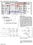
Look Figure 1 : Block Diagram of Inverter Power Stage
http://www.irf.com/technical-info/whitepaper/cic1200v.pdf

..........................................................................................................

Inverter_Pwr_Stage_cic_p01.jpg

KAK
 
look how to test 6 IGBTs with free wheeling diodes
and 3-phase bridge same way as separate diodes


Look Figure 1 : Block Diagram of Inverter Power Stage
http://www.irf.com/technical-info/whitepaper/cic1200v.pdf

..........................................................................................................

View attachment 62493

KAK


But what to do with NLU while testing this IGBT power module & what to do with converter circuit ?

Just test the 6 diodes as a pair of 3 diodes with DMM ? or treat them an a single diode ?

Are you referring to this post :
" How to test this IGBT module BSM 50 GD120DN2E3226 having 6 IGBTs with free wheeli
I drew instructions.....................

Test 6 pcs IGBT module same way as 3 separate IGBT pairs :
"

thanks for your phenomenal answers & replies *** Bless Ya
 
Last edited:

Are you referring to this post :
" How to test this IGBT module BSM 50 GD120DN2E3226 having 6 IGBTs with free wheeli
I drew instructions.....................:

Yes.

But what to do with NLU while testing this IGBT power module

Nothing.............Just do as shown in above post.

Test diodes same way as in diode bridge, each diode separately.

I think that NLU part can not be tested separately,
It is only possible to compare conductivity between gate terminal and the corresponding emitter
in each IGBT.
Test with multimeter diode-range in both polarity by changing meter wires ( same as in diode test )
Values should be same with each IGBT-gate.

In attached picture in...........
https://www.edaboard.com/threads/227364/#post969472
has simple explanation of NLU principle .

KAK
 
Yes.


Nothing.............Just do as shown in above post.

Test diodes same way as in diode bridge, each diode separately.

I think that NLU part can not be tested separately,
It is only possible to compare conductivity between gate terminal and the corresponding emitter
in each IGBT.
Test with multimeter diode-range in both polarity by changing meter wires ( same as in diode test )
Values should be same with each IGBT-gate.

In attached picture in...........
https://www.edaboard.com/threads/227364/#post969472
has simple explanation of NLU principle .

KAK


thanks a lot .......

1) so there are total 13 diodes , so test all of the 13 diodes separately both in reverse bias & forward bias condition ? am i right ???

For testing IGBTs having Gates : Gb (7), Gx (8) , Gy (9) & Gz (10) the Emitter is same i.e. E (11), Am i right ??? Can't we take "N" as Emitter because they both shorted out to each other ( for testing the IGBTs whose Gate's names are mentioned above ) ????


2) For testing IGBTs having Gates : Gu (1), Gv (3) , Gw (5) the Collector is same i.e. P1 , Am i right ???

3) And taking Emitters Eu (2) for IGBT whose gate is Gu (1), Ev (4) for IGBT whose gate is Gv (3) ,
Ew (6) for IGBT whose gate is Gw (5) ... Am i right , sir ???

4) Can't we take U as emitter of the IGBT whose gate is Gu (1) instead of Eu (2) ?
Similarly, Can't we take V as emitter of the IGBT whose gate is Gv (3) instead of Ev (4) ?
And, Similarly, Can't we take W as emitter of the IGBT whose gate is Gw (5) instead of Ew (6) ?

Cause U is shorted out to Eu (2)
Similarly, V is shorted out to Ev (4)
And, W is shorted out to Ew (6) .....

5) For Testing diodes individually :

a) For Converter Circuit (the diodes on the above) : cathode is P & Anode is R, S & T. Am i right ?
b) For Converter Circuit (the diodes on the bottom) : cathode is R, S & T & Anode is N or E (11). Am i right ?

c) For Brake Circuit : cathode is P1 & Anode is B. Am i right ?

d) For Inverter Circuit (the diodes on the above) : cathode is P1 & Anode is Eu, Ev & Ew OR (U, V & W Respectively). Am i right ?
e) For Inverter Circuit (the diodes on the bottom) : cathode is U, V & W & Anode is N or E (11). Am i right ?


Kindly, answer these thanks a lot
 

Yes, every component tested as a separate part.

If it helps you , imagine two separate rows of components
blue and green as shown in picture below.................

7MBR25NE120_IGBT_MOD_01up&do.jpg

KAK
 
Yes, every component tested as a separate part.

If it helps you , imagine two separate rows of components
blue and green as shown in picture below.................

View attachment 62531

KAK

bundle of thanks man

the split pictures you sent with green boundary & other with blue boundary are proving that whatever i understood was absolutely right ? thanks to you man
 

Status
Not open for further replies.

Similar threads

Part and Inventory Search

Welcome to EDABoard.com

Sponsor

Back
Top