Continue to Site

Welcome to EDAboard.com

Welcome to our site! EDAboard.com is an international Electronics Discussion Forum focused on EDA software, circuits, schematics, books, theory, papers, asic, pld, 8051, DSP, Network, RF, Analog Design, PCB, Service Manuals... and a whole lot more! To participate you need to register. Registration is free. Click here to register now.

How to simulate the transconductor?

Status
Not open for further replies.

M.B.

Member level 2
Joined
Mar 31, 2008
Messages
47
Helped
2
Reputation
4
Reaction score
2
Trophy points
1,288
Location
TUNISIA
Activity points
1,561
Hello to all,

Now I design this circuit: CMOS transconductor using varing Bias Triode Transistors for a GM-C filter.
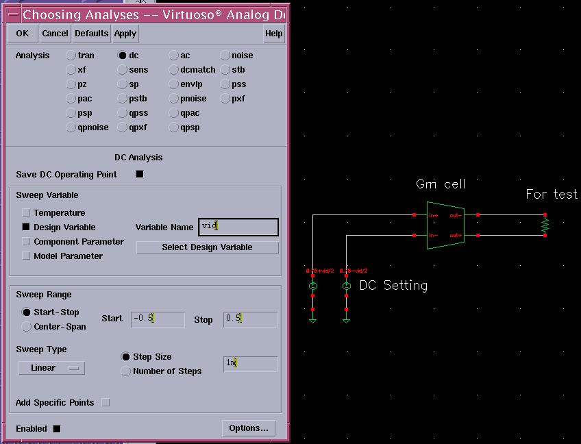
I want to know how to simulate the transconductance of this circuit using CADENCE? (or how to know the value of the transconductance gm of a circuit by simulation?)

Also, i want to know what are the important specifications of this circuit?


Thanks to all.
 

The answer is simple and easy: Use the definition of the parameter you want to simulate.
In your case: According to the definition of the transconductance you should measure (simulate) the change in output current devided by the corresponding change in input voltage. By doing this, you have two alternatives:
1.) DC analysis: Simulate the output-input characteristics (curve) by displaying
Iout as a function of VDCin. Then, you can find the gm for each point you want (slope of the curve).
2.) AC analysis: Choose a bias point and display the ratio Iout,ac/Vac,in.
In this case, you get the frequency behaviour of the gm value.
 

How to expand the linear range of the transconductor?
 

In addition to the previous answer to simulate the effective Gm of the cell you can create ac short at the output and measure the output ac current for input ac voltage. For this purpose, set the bias point, connect big enough capacitance to each output node and a 0v voltage source between the other ends of the capacitances. So, in effect there is a 0v source between the outputs but separated by big capacitors from the outputs, because you don't want to disturb the biasing. Measure the current through this voltage source for 1 input ac voltage. This will be the small signal effective Gm in frequency domain.
 

jingxuelu said:
How to expand the linear range of the transconductor?

If the question is related to some external circuitry, the only way is to use negative feedback.
 

Hi, I attach my simulation method, wish can help u (i use cadence to simulate)
1) change the dc bias voltage to differential : Vbias+Vid/2 and Vbias-Vid/2
2) set the DC analyze shown in picture
3) save the output current
4) run DC simulation, and then use calculator to get deriv Iout/Vin
Then u can get the Gm of the circuit with Input voltage ^^


yixiusky said:
Hi, I attach my simulation method, wish can help u (i use cadence to simulate)
1) change the dc bias voltage to differential : Vbias+Vid/2 and Vbias-Vid/2
2) set the DC analyze shown in picture
3) save the output current
4) run DC simulation, and then use calculator to get deriv Iout/Vin
Then u can get the Gm of the circuit with Input voltage ^^


i try to complete the dc analysis as you told,but i wonder:
vid is a dc signal or a sine wave?
how to get the output current? connect a resistor or a voltage source?
how to use the calculator to get the deriv Iout/Vin?
 

Status
Not open for further replies.

Part and Inventory Search

Welcome to EDABoard.com

Sponsor

Back
Top