pancho_hideboo
Advanced Member level 5
- Joined
- Oct 21, 2006
- Messages
- 2,847
- Helped
- 767
- Reputation
- 1,536
- Reaction score
- 733
- Trophy points
- 1,393
- Location
- Real Homeless
- Activity points
- 17,490
No in your case.But fundamental frequency is output frequency,isn't it?
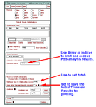
If you provide it, I can confirm from various aspects.And if you have to get the netlist, I will try to apply for an authority to paste the netlist here.
I don't think so.and somebody has the same issue as mine.
I think simply fundamental frequency is not correct.
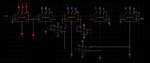
At least, frequency at "P4" can be never 200MHz/4.
Again surely confirm time period of all nodes.
Attachments
Last edited: