Continue to Site

Welcome to EDAboard.com

Welcome to our site! EDAboard.com is an international Electronics Discussion Forum focused on EDA software, circuits, schematics, books, theory, papers, asic, pld, 8051, DSP, Network, RF, Analog Design, PCB, Service Manuals... and a whole lot more! To participate you need to register. Registration is free. Click here to register now.

How to simulate fully differential amplifier

Status
Not open for further replies.

walker5678

Full Member level 3
Joined
May 17, 2006
Messages
179
Helped
7
Reputation
14
Reaction score
3
Trophy points
1,298
Activity points
2,493
how to simulate differential amplifier gain

Hi ,
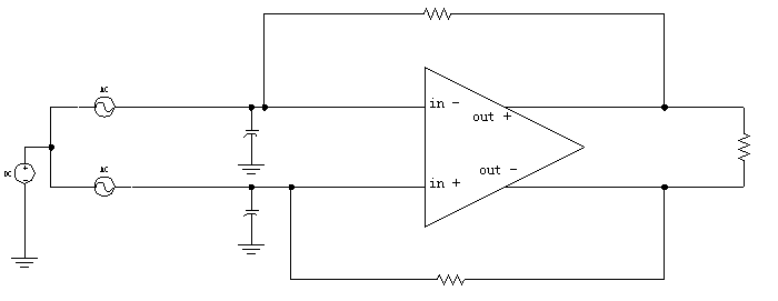
I am designing a fully differential amplifier, and want to simulate the frequency response of the Open Loop Gain and the Phase. Any one know how to set up the simulation circuit? Is it the same as simulating single output amplifier?

Thanks a lot!
 

ac simulation differential amplifier

I think it is the same as simulating single-ended amp.
Just that you place 1V AC to Vin_p and -1V AC to Vin_n and construct the feedback path that open to AC but closed to DC.
 

how to simulate open loop amplifier

"place 1V AC to Vin_p and -1V AC to Vin_n"

in the single ended simulation, we only place 1V AC to Vin_p and feedback the DC signal to Vin_n. So if also place AC signal to Vin_n, then the AC signal will be shorted by the large capacitor connected to GND, so how to implement it ?

6_1160701751.gif
 

Put 0.5 VAC to the in+ and -0.5 VAC to in-. Measure the output voltage as out+ - out-.
 

Walker,
Remove the two caps at the input and the resistor at the output.
Put a big (10H) inductor to the feedback paths, the feedback resistors should be big too.
I think this works if there is no current flow through the feedback path. If there is, u need to reduce the feedback resistors to avoid saturation, but your open loop gain plot will not be accurate.

Hope this helps.

Put 0.5 VAC to the in+ and -0.5 VAC to in-. Measure the output voltage as out+ - out-.
You are correct, but it has the same effect as "place 1V AC to Vin_p and -1V AC to Vin_n" and measure out+ only.
 

Yes, of cource you can simulate as single-ended OP AMP.
put AC 1 on in+ and connect in+ and out- with large resistor, and like single-ended, conect in- and out+ with large resistor and large cap, then measure (out+-out-) for open loop Gain and PM.
 

Hi, sengyee

I think you are right, that's the way to feedback DC signal while avoid AC signal. Thanks.

Added after 13 minutes:

Another question, why should i remove the resistor from the output? I found that when this resistor is connected , the Open Loop Gain simulation result becomes much lower than that without the resistor.
 

Because you form another feedback loop. If your opamp output do not have buffer, it actually reduces output impedance, hence reduces overall open loop gain.
 

Status
Not open for further replies.

Part and Inventory Search

Welcome to EDABoard.com

Sponsor

Back
Top