Continue to Site

Welcome to EDAboard.com

Welcome to our site! EDAboard.com is an international Electronics Discussion Forum focused on EDA software, circuits, schematics, books, theory, papers, asic, pld, 8051, DSP, Network, RF, Analog Design, PCB, Service Manuals... and a whole lot more! To participate you need to register. Registration is free. Click here to register now.

How to send an analog voltage a long distance.

Status
Not open for further replies.

cupoftea

Advanced Member level 5
Joined
Jun 13, 2021
Messages
2,523
Helped
54
Reputation
108
Reaction score
110
Trophy points
63
Activity points
13,202
Oops sorry, this was meant for the analog forum on this website
Hi,
Supposing you have an analog signal voltage you want to send a long way on a PCB....maybe even up headers and on to a different PCB. Due to SMPS's on the PCB(s), the ground potential at different plcaes may be different......you obviously always want the signal with respect to local ground to be the same value.
How do you ensure this?
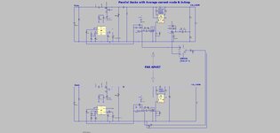
Would you eg use a AD8226 InAmp and send it like the following?

AD8226


Oops sorry, this was meant for the analog forum.
 

Attachments

  • Pllel Bucks with ACM and InAmp.jpg
    Pllel Bucks with ACM and InAmp.jpg
    130.4 KB · Views: 75

Hi,

Either
* as current, or
* NOT referenced to GND, or
* transformed digital (as PWM or code)
* or a lot of other ways: as frequency, modulated....

Purely analog: indeed it does not matter much if you use a differential pair, or a GND_sense or any other reference.
Best is to give both signals the same source impedance, wire them in parallel, and use the same load impedance.

Klaus
 
Differential signalling is generally a good idea. Systems are designed for specific bandwidth and dynamic requirements, so I would ask about it before deciding any details.
 
Fiber optics.
Convert analog >> Digital........................Digital>> Analog
Wireless

What is distance and needed data rate ?


Regards, Dana.
 
Purely analog: indeed it does not matter much if you use a differential pair, or a GND_sense or any other reference.
Don't understand why you say that(?).
Certainly if there is a GND potential difference between the sending and receiving points, than it does make a difference.
Sending the signal differentially to a receiver with good common-mode signal rejection will minimize that difference.
 
Sending the signal differentially to a receiver with good common-mode signal rejection will minimize that difference.
Thanks, so would you say the shown method in the top post, being non-differential, is a poor method?
 

    JWHassler

    Points: 2
    Helpful Answer Positive Rating
Thanks Klaus.
Your top circuit looks by far the best to me. And i would like if poss, to ask for the part number of the "Thing" on the left that gives the diff pair output, from the single ended measurement. As i would need to "make" that out of more than one part.
 

Hi,
There's a considerable difference in high frequency common mode behaviour.
I did not say they have identical behaviour.

But as far as I can see in all 3 cases the GND bounce affects both signals the same way. As in delta-V and dV/dt.

The 3 schematics just depict what I´ve written in post#2.
For sure one can modify/improve them. E.g. by installing common mode filters in front of the receivers.

*****
Detailed view:
Case: pure differential. vs "GND_sense" method
* Diff_out amplifier. I´d say the common mode output voltage (DC) does not matter much for the function (correct me if I´m wrong). So I set it to 1V DC. Now let´s say the input voltage is 2V.
--> the pair output voltages will be +2V and 0V (transmitter side)

* Same conditions for the "GND_sense method". 2V input signal.
--> the ouput voltages will be +2V and 0V (transmitter side)

So in both cases both signals carry the same voltage and have the same source impedance.
Thus I´d say the receiver needs to treat them the same. No difference in output behaviour.
The receiver doesn´t know what´s on the transmittter side, it sees the voltages (and could see the impedance)

*****
GND_sense mode surely is worse with the (often used) "simple GND_sense", where no impedance match is done.
(reference line directly connected to GND instead via the impedance match circuit)
Then there is a "signal line" with it´s impedance and an GND line with a different impedance.
For sure common mode noise hase different impact on the two signal lines due to their different impedance.

Klaus
 
To assess any of these points, we need an idea of signal speed (can be 100 Hz or 100 MHz) and dynamic range (can be 10 or 24 bit).
 
To assess any of these points, we need an idea of signal speed (can be 100 Hz or 100 MHz) and dynamic range (can be 10 or 24 bit).
Thanks, AYK, the speed of the "share" signal in pllel SMPS's, can be less than 100Hz. There being no need for it to be faster than 100Hz in most cases.
 

Yes i like the 4-20mA best , though cost of interfacing to it is prohibitive for us.
As such, i prefer the way the UCC29002 does it...but it breaks all the rules of analog signal transmission, and simply sends the "share" signal as a single wire signal between modules...

UCC29002 Load share controller (page 15)

UCC29002
 

Status
Not open for further replies.

Similar threads

Part and Inventory Search

Welcome to EDABoard.com

Sponsor

Back
Top