Continue to Site

Welcome to EDAboard.com

Welcome to our site! EDAboard.com is an international Electronics Discussion Forum focused on EDA software, circuits, schematics, books, theory, papers, asic, pld, 8051, DSP, Network, RF, Analog Design, PCB, Service Manuals... and a whole lot more! To participate you need to register. Registration is free. Click here to register now.

How to optimize S-Parameter?

imtiaz369

Member level 1
Joined
Jul 8, 2021
Messages
39
Helped
0
Reputation
0
Reaction score
0
Trophy points
6
Activity points
429
I've attached three pictures. The first is S-parameter derivatives, and you can see the most impact by the loss tangent, copper thickness, and substrate thickness, which are constant. I can't change these variables. I'm working with FR4.

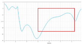
Well, the second one is my S11 graph. I want to improve the S-parameter more from 5-8GHz. But I can not able to do this. I tried to use all the parameters but could not. I used Pattern Search Optimization, Quasi-Newton Optimization, and parametric of available variables.

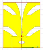
the third picture is of my antenna. it is a Vivaldi antenna. so anyone have an idea or suggestion, on how can I improve my s11 by more than -20dB!!!

1701288167773.png


1701288192200.png


1701288290750.png
 
As already mentioned, FR4 is not useful at these frqeuencies, because it is too lossy. Even if you can reach good S11, the antenna gain will be poor.

I tried to use all the parameters but could not.

None of these parameters is suitable to optimize antenna bandwidth. You use a fancy layout, did you study the influence of geometry parameters? Properly designed Vivaldi antennas can be really wideband. However, your goal of -20dB return loss is tough, do you really need that?
 
As already mentioned, FR4 is not useful at these frqeuencies, because it is too lossy. Even if you can reach good S11, the antenna gain will be poor.


None of these parameters is suitable to optimize antenna bandwidth. You use a fancy layout, did you study the influence of geometry parameters? Properly designed Vivaldi antennas can be really wideband. However, your goal of -20dB return loss is tough, do you really need that?
first of all, I can not change the substrate. Could you please say a little bit more about the "influence of geometry parameters"? -18/16 dB is also okay, actually in fabrication it degrades around -5/6 dB, so I have to achieve around 18-20 dB around the 4-9GHz range...
 
How can I improve the S11 of a Vivaldi antenna to less than -20dB for 5-9 GHz bandwidth? The material is FR4, so what can I include here to improve the geometry?
 

Attachments

  • 1.png
    1.png
    60.2 KB · Views: 41
  • 2.png
    2.png
    119.9 KB · Views: 44
so what can I include here to improve the geometry?
This is a strange question. Someone designed the layout with all those dimensions, such as hole diameter or taper curvature. All these layout details are the major design parameters, the substrate is just one additonal influence.

But if you are limited to using FR4, you might just give up now, the antenna performance (gain) will be poor even if you achieve perfect matching.
 
But i can not change FR4, other than this, is there any other way?
You can try another type of antenna. I have used FR4 at 20GHz+ for EBG antenna and AFSIW antenna (google on EBG mushroom structure using VIAs and Air Filled Substrate Integrated Waveguides). With AFSIW trick is that you don't use dielectric. To eliminate electrical contact problem for AFSIW, check this paper:
(just look at the image, no need to download the paper). Or maybe some H-plane horn using RGW (using EBG "mushrooms"). The trick is to minimize power density inside FR4 substrate and use air. The main problem I had is coupling between MMIC and waveguide, this part is still lossy. It is probably not what you want, just FYI. Maybe you will have some new ideas after looking into it.
 

LaTeX Commands Quick-Menu:

Part and Inventory Search

Welcome to EDABoard.com

Sponsor

Back
Top