Continue to Site

Welcome to EDAboard.com

Welcome to our site! EDAboard.com is an international Electronics Discussion Forum focused on EDA software, circuits, schematics, books, theory, papers, asic, pld, 8051, DSP, Network, RF, Analog Design, PCB, Service Manuals... and a whole lot more! To participate you need to register. Registration is free. Click here to register now.

how to model a nonlinear resistor controlled by current in SPICE software?

Status
Not open for further replies.

tolly8210

Newbie level 4
Newbie level 4
Joined
Mar 22, 2013
Messages
7
Helped
0
Reputation
0
Reaction score
0
Trophy points
1,281
Visit site
Activity points
1,360
Dear All,

I want to model a nonlinear resistor behavior whose V-I relation is as V=R1*I+R2*I^3 = (R1+R2*I^2)I.
I face this problem when I try to establish a equivalent circuit model for a nonlinear mechanical system.

For a linear single DOF mechanical system. Mx''+Dx'+Kx=F, where M is the mass; D damping, K stiffness, F force, x is displacement. if we analogize it as a electrical system: Lq''+Rq'+q/C=V, where L is equivalent to M, R is equivalent to D, 1/C is equivalent to K, voltage source V is equivalent to F, charge q is equivalent to x. by such equivalent circuit model, we can predict the mechanical system response by electrical simulation in SPICE software.

Now, I have a nonlinear system. The damping term is nonlinear, D1x'+D2x'^3 (for circuit equivalence, R1*I+R2*I^3=(R1+R2*I^2)*I ). if I can model such nonlinear resistance behavior, I can predict the mechanical performance by circuit simulation.

Any suggestion or implementation experience?

Thanks in advance.
 

Any suggestion or implementation experience?
This sort of thing is fairly easy with SIMETRIX SIMplis. That's the free SPICE simulation software I use.

As the help file says:

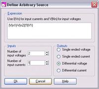
The schematic menu Place|Analog Behavioural|Non-linear Transfer Function brings up the following dialog


Specify the number of input voltages and currents you require. All voltage inputs are single-ended and all input currents are differential. In the expression box, you must specify an equation relating the output to the inputs.......

Example:


I don't know how you'd do it with other SPICE software.
 

This sort of thing is fairly easy with SIMETRIX SIMplis. That's the free SPICE simulation software I use.

As the help file says:


Example:


I don't know how you'd do it with other SPICE software.

Thanks for your reply, guys
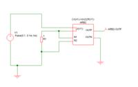
my problem is kind of shown in below figure. the output from the arbitary source will be connected in series into the circuit.
5153855100_1363952460.gif

The system is Lq''+q/C+[-R1*q'+R2*q'^3]=0
it is a self-excited system. initially, a small disturbance (some initial charge from capacitor) happens, due to the negative resistance -R1 (negative damping), the oscillation will continue to be amplified. when the q is sufficiently large and R2*q'^3 dominates, the overall damping will be back to positive value, then the oscillation will stop increasing and stay at certain amplitude (limit cycle oscillation).
Not sure whether the method you proposed can be capable of modeling this system.

For a conventional system, the resistor is positive and linear (Lq''+q/C+R1*q'=0). the initial disturbance (charge in the capacitor) will quickly be attenuated because of the positive damping effect of the resistor.
 

Not sure whether the method you proposed can be capable of modeling this system.
Probably/maybe. If you want to model: V=R1*I+R2*I^3, you would need to use an arbitrary source with one current input and one voltage output.

Then for example, if R1 = -7ohms and R2 = 3 ohms, the expression you enter would be: -7*I(V1)+3*I(V1)^3

Experiment:
I assume you want to model it as a 2 terminal device with that equation giving the relationship between the current through it and the voltage across it, so I used a differential voltage output and connected to itself like this:


Driven with a 2 Amp rms sine wave source, the voltage across it looks like this:


Here's a graph of voltage vs current:


As you can see, the trouble with this example is that the same voltage can correspond to three different currents. So the calculations may not converge, depending what it's connected to and how it's driven.

BTW: you mentioned this is to model a mechanical system. Is it possible to have negative damping in a mechanical system? I know negative stiffness is fairly easy to implement, but I've never heard of negative damping.

- - - Updated - - -

Anyway, it seems to work for the kind of oscillator you mentioned.
(Yes, I'm bored and having fun with this. :grin:)


Last edited:

Dear godfreyl

Many many thanks, the last figure of oscillator seems just what I want. In practice, the negative damping and negative stiffness are both possible. For example, you may hear the "flutter" phenomenon of a flight wing. The force from aerodynamics is -D1*x'+D2*x'^3, which is a nonlinear damping effect. if the D1 is larger than the mechanical damping D0, the overall linear damping term is negative, in such case, the wing will vibrate with increasing amplitude. however, the amplitude will not infinitely increase because the cubit term of damping D2*x'^3 will limit its amplitude in certain level (beyond certain level, the cubic term will dominate and the overall damping will be positive again).

BTW, you add some initial condition (equivalent to mechanical disturbance) for capacitor (or inductor), right? otherwise, the oscillation will not start.


Probably/maybe. If you want to model: V=R1*I+R2*I^3, you would need to use an arbitrary source with one current input and one voltage output.

Then for example, if R1 = -7ohms and R2 = 3 ohms, the expression you enter would be: -7*I(V1)+3*I(V1)^3

Experiment:
I assume you want to model it as a 2 terminal device with that equation giving the relationship between the current through it and the voltage across it, so I used a differential voltage output and connected to itself like this:


Driven with a 2 Amp rms sine wave source, the voltage across it looks like this:


Here's a graph of voltage vs current:


As you can see, the trouble with this example is that the same voltage can correspond to three different currents. So the calculations may not converge, depending what it's connected to and how it's driven.

BTW: you mentioned this is to model a mechanical system. Is it possible to have negative damping in a mechanical system? I know negative stiffness is fairly easy to implement, but I've never heard of negative damping.

- - - Updated - - -

Anyway, it seems to work for the kind of oscillator you mentioned.
(Yes, I'm bored and having fun with this. :grin:)


BTW, you add some initial condition (equivalent to mechanical disturbance) for capacitor (or inductor), right? otherwise, the oscillation will not start.
Yes, it's the "IC" component above "Vout". It indicates an initial condition of 0.1V at the top of the capacitor.
 

    V

    Points: 2
    Helpful Answer Positive Rating
Dear buddy,

thanks for your help. I download the software and have almost solved this modeling problem. In this problem, I need to further add an ideal transformer which give some error (compared with ode45 simulation with Matlab). Could you PM me your email so that I send you some of my simulation results.

Best,


Yes, it's the "IC" component above "Vout". It indicates an initial condition of 0.1V at the top of the capacitor.
 

Rather post it here so others can see it and comment too. I prefer not to give out my email address anyway.
 

Dear godfreyl

Okay, see the following figures.

The equations of the system:
L1q''+R1q'+q/C1-r1*q'+r3*q'^3+n*V=0
where,
L1=0.02
R1=0.01
C1=0.02 initial condition = 0.0001uV
r1=0.0202,r2=0.1502
n=0.00005 (primary to secondary turn ratio)
V is the voltage across the capacitor C2(=25nF)

This is the schematic of the system, I add an ideal transformer and a capacitor.
schematic.png

I set the ideal transformer use default value except the secondary to primary turn ratio 1/n.
setup of ideal transformer.png

I get the Simetrix simulation results as follows:
results.png
The peak current (q') is 0.3A and the V peak is around 4Volt

However, if I simulate the problem with matlab ode45, the results as follows:
Matlab_velocity.png (velocity is equivalent to current)
Matlab_voltage.png

we can see the velocity (current) is consistent (0.3) but the voltage is different (in matlab, Vpp=24V). the matlab results are correct.

The err of Simetrix results from the setting of ideal transformer. the default value "primary 1 inductance" seems greatly affect the simulation results (default value=10uH). If I change to a larger value, say 1mH.
result2.png
we can see the results are close to the matlab results. actually, if we see the zoom-in view:
result2-zoom in.png
The peak-peak V is 24volt, which is consistent with matlab results by using a large "primary 1 inductance"
The problem is that using a larger "primary 1 inductance", the results seems to be superposed with another low-frequency harmonic response. Such phenomenon will be more significant if i choose a larger inductance.

In a word, the ideal transformer in Simetrix not behaves as real "ideal". what's the function of "primary 1 inductance"? and how to properly set this value so that I could get a correct results as Matlab ones (without superposed harmonic response).

hope I have made my problem regarding ideal transformer clear.

Thanks,


Rather post it here so others can see it and comment too. I prefer not to give out my email address anyway.
 
Last edited:

Sounds like an "artificial" problem. An ideal transformer has a parallel inductance in usual understanding. How is the transformer modelled in Matlab?
 

The primary inductance is equivalent to an inductor connected across the primary winding of the transformer. Real transformers do have inductance so it's fair to include it in the "ideal transformer" model.

Anyway, I see there's also a "ideal DC transformer" without inductance. If you use that instead, it may solve the problem.
 

Dear godfreyl

I tried ideal DC transformer, no current output now!


The primary inductance is equivalent to an inductor connected across the primary winding of the transformer. Real transformers do have inductance so it's fair to include it in the "ideal transformer" model.

Anyway, I see there's also a "ideal DC transformer" without inductance. If you use that instead, it may solve the problem.

- - - Updated - - -

Dear FvM

In matlab, just need to write the state space form of the differential equations of the system, then call ode45 to do numerical simulation for you. No need to build the circuit.


Sounds like an "artificial" problem. An ideal transformer has a parallel inductance in usual understanding. How is the transformer modelled in Matlab?
 

In matlab, just need to write the state space form of the differential equations of the system
Yes, that was my assumption do. So where is the "transformer" in the differential equation?
 

n*V,
n represents the transformer turn ratio
Yes, but a transformer is a bidirectional device, it's not defined in the differential equation (no equation for currents).

It's however quite easy to transform C2 to the primary.
 

Status
Not open for further replies.

Part and Inventory Search

Welcome to EDABoard.com

Sponsor

Back
Top