Continue to Site

Welcome to EDAboard.com

Welcome to our site! EDAboard.com is an international Electronics Discussion Forum focused on EDA software, circuits, schematics, books, theory, papers, asic, pld, 8051, DSP, Network, RF, Analog Design, PCB, Service Manuals... and a whole lot more! To participate you need to register. Registration is free. Click here to register now.

[SOLVED] how to merge two adc codes to one code for same mcu

Status
Not open for further replies.

Muhammad.Saad

Newbie level 6
Newbie level 6
Joined
Mar 11, 2014
Messages
12
Helped
0
Reputation
0
Reaction score
0
Trophy points
1
Location
Islamabad, Pakistan
Visit site
Activity points
105
hi
I just want to know how to manage two different codes to one code, as i have one code for digital voltmeter and second for voltage limits. but I want to make both of them working on same controller. the code is pasted below:

code # 1:


Code C - [expand]
1
2
3
4
5
6
7
8
9
10
11
12
13
14
15
16
17
18
19
20
21
22
23
24
25
26
27
28
29
30
31
32
33
34
35
36
37
38
39
40
41
42
//Function Prototypes
 void floattostring(double FP_NUM);
 double FP_NUM, volt;
 char string[6];
 //Sub Function
 void floattostring(double FP_NUM) {
 double fpnumber;
 long int befdec, aftdec;
 fpnumber = FP_NUM;
 befdec = fpnumber; // Fractional part is truncated
 // 12.163456 becomes 12
 aftdec = fpnumber * 100; // 12.163456 becomes 1216
 aftdec = aftdec - (befdec * 100); // 1216 - 1200 = 16
 }
 void main() {
 TRISA = 0b00000001;
 PORTA = 0b00000000;
 TRISC = 0b00000111;
 PORTC = 0b00000000;
 TRISD = 0b00000000;
 PORTD = 0b00000000;
 ADCON1 = 0b10001110;
 CMCON = 0b00000111;
 while(1) {
 volt = ADC_Read(0);
 volt = volt * 0.0305498981670061;
 volt = volt * 0.9612303748798462;
 floattostring(volt);
 if(volt > 27.0) { // Change value here
 PORTD.F0 = 1;
 }
 else if(volt < 27.0) { // Change value here
 PORTD.F0 = 0;
 }
 if(volt > 9.25) { // Change value here
 PORTD.F4 = 0;
 }
 else if(volt < 9.25) { // Change value here
 PORTD.F4 = 1;
 }
 }
 }


code # 2


Code C - [expand]
1
2
3
4
5
6
7
8
9
10
11
12
13
14
15
16
17
18
19
20
21
22
23
24
25
26
27
28
29
30
31
32
33
34
35
36
37
38
39
40
41
42
43
44
45
46
47
48
49
50
51
52
53
54
55
56
57
58
59
60
61
62
63
64
65
66
67
68
69
70
71
72
73
74
75
76
77
78
79
80
81
unsigned int adc_rd0,tlong;
 unsigned short mask(int num)
 {
 switch (num)
 {
 case 0 : return 0xC0;
 case 1 : return 0xF9;
 case 2 : return 0xA4;
 case 3 : return 0xB0;
 case 4 : return 0x99;
 case 5 : return 0x92;
 case 6 : return 0x82;
 case 7 : return 0xD8;
 case 8 : return 0x80;
 case 9 : return 0x90;
 case 10: return 0x40;
 case 11: return 0x79;
 case 12: return 0x24;
 case 13: return 0x30;
 case 14: return 0x19;
 case 15: return 0x12;
 case 16: return 0x02;
 case 17: return 0x78;
 case 18: return 0x00;
 case 19: return 0x10;
 }
 }
 unsigned short shifter, portb_index;
 unsigned int digit, number;
 unsigned short portb_array[4];
 void interrupt()
 {
 PORTC = 0;
 PORTB = portb_array[portb_index];
 PORTC = shifter;
 shifter <<= 1;
 if(shifter > 8u)
 shifter = 1;
 portb_index ++ ;
 if (portb_index > 3u)
 portb_index = 0;
 TMR0 = 0;
 INTCON = 0x20;
 }
 void display()
 {
 digit = number % 10u;
 portb_array[0] = mask(digit);
 digit = (number / 10u) % 10u;
 portb_array[1] = mask(digit);
 digit = (number / 100u) % 10u+10;
 portb_array[2] = mask(digit);
 digit = number / 1000u;
 portb_array[3] = mask(digit);
 }
 void main()
 {
 // port initialization...
 TRISB = 0x00; // Set PORTB direction to be output
 PORTB = 0xff; // Turn OFF LEDs on PORTB
 TRISC= 0x00; // Set PORTB direction to be output
 PORTC = 0x00;
 TRISA = 0xFF; // all input
 digit = 0;
 portb_index = 0;
 shifter = 1;
 number = 0; //initial value;
 // tiemr0 settings...
 OPTION_REG = 0x80; // Set timer TMR0;
 TMR0 = 0;
 INTCON = 0xA0; // Disable interrupt PEIE,INTE,RBIE,T0IE
 while(1)
 {
 // Read Battery voltage
 ADCON0 = 0b00000001;
 adc_rd0 = ADC_Read(0); // A/D conversion. Pin RA2 is an input.
 tlong = (float)adc_rd0 *1.96078431372549; // Convert the result in millivolts
 number = tlong;
 display();
 }//Endless loop;
 }//End

 
Last edited by a moderator:

Why do you want to merge the codes? The second code uses 7 Segment display to display ADC value. The first code is written by me.
 

thanks milan your code really helped me.
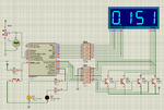
I want to use these codes for a same mcu. when voltage on 7segment is higher than 4.5 volts first led should on, and when voltage is less than 1.5 volts second led should on. I am also attaching proteus file plz check it. actually I want to make over under voltage limits for digital voltmeter. looking for help.
 

Attachments

  • 873.rar
    21.7 KB · Views: 67

You need to use Transistors (BC547) to drive the enable/disable pin of SSD. You will need 3 BC547s.
 

The file you posted doesn't contain complete mikroC Project files. Zip and post complete mikroC files. Mention what SSD are you using, CC or CA type? What is the range of voltage you want to measure?
 

SSD i am using is CA. the range of voltage i want to measure is from 0 to 5 volts as shown in proteus file. but i want to add one more feature , i.e voltage limitation.
When voltage value which is displaying on ssd is less than 1.5 volt the led which is connected with port D pin o should on.
When voltage value which is displaying on ssd is higher than 4.5 volt the led which is connected with port D pin 4 should on.

i have codes for both (ssd and voltage limiatation) but i want to make one project file, actually i want to merge two codes in one mikroc project
i am sending the complete project but i couldn't add tthe feature of voltage limitation which is mentioned above
 

Attachments

  • complt.rar
    71.2 KB · Views: 72

Working project attached. See sim.avi video inside .rar file. I have used Proteus 8.1 SP1. If you have older version of Proteus then redraw the circuit in that version.

When voltage value which is displaying on ssd is less than 1.5 volt the led which is connected with port D pin o should on.
When voltage value which is displaying on ssd is higher than 4.5 volt the led which is connected with port D pin 4 should on.

There is no PORTD in PIC16F873A. I have used PORTC instead.

103297d1395081224-ssdvm.png
 

Attachments

  • ssdvm.png
    ssdvm.png
    97 KB · Views: 115
  • SSD VM.rar
    447.5 KB · Views: 72
Hi milan thanks very much it really helped me. Once again thanks

- - - Updated - - -

:-D:-D:-DHi milan thanks very much it really helped me. Once again thanks

- - - Updated - - -

:-D:-D:-DHi milan thanks very much it really helped me. Once again thanks
 

Status
Not open for further replies.

Similar threads

Part and Inventory Search

Welcome to EDABoard.com

Sponsor

Back
Top