Continue to Site

Welcome to EDAboard.com

Welcome to our site! EDAboard.com is an international Electronics Discussion Forum focused on EDA software, circuits, schematics, books, theory, papers, asic, pld, 8051, DSP, Network, RF, Analog Design, PCB, Service Manuals... and a whole lot more! To participate you need to register. Registration is free. Click here to register now.

How to make SG3525's Output Voltage to 5V?

iamkim

Newbie
Joined
Mar 20, 2024
Messages
3
Helped
0
Reputation
0
Reaction score
0
Trophy points
1
Activity points
35
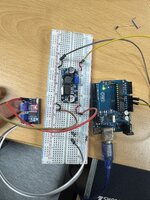
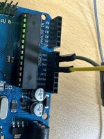
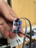
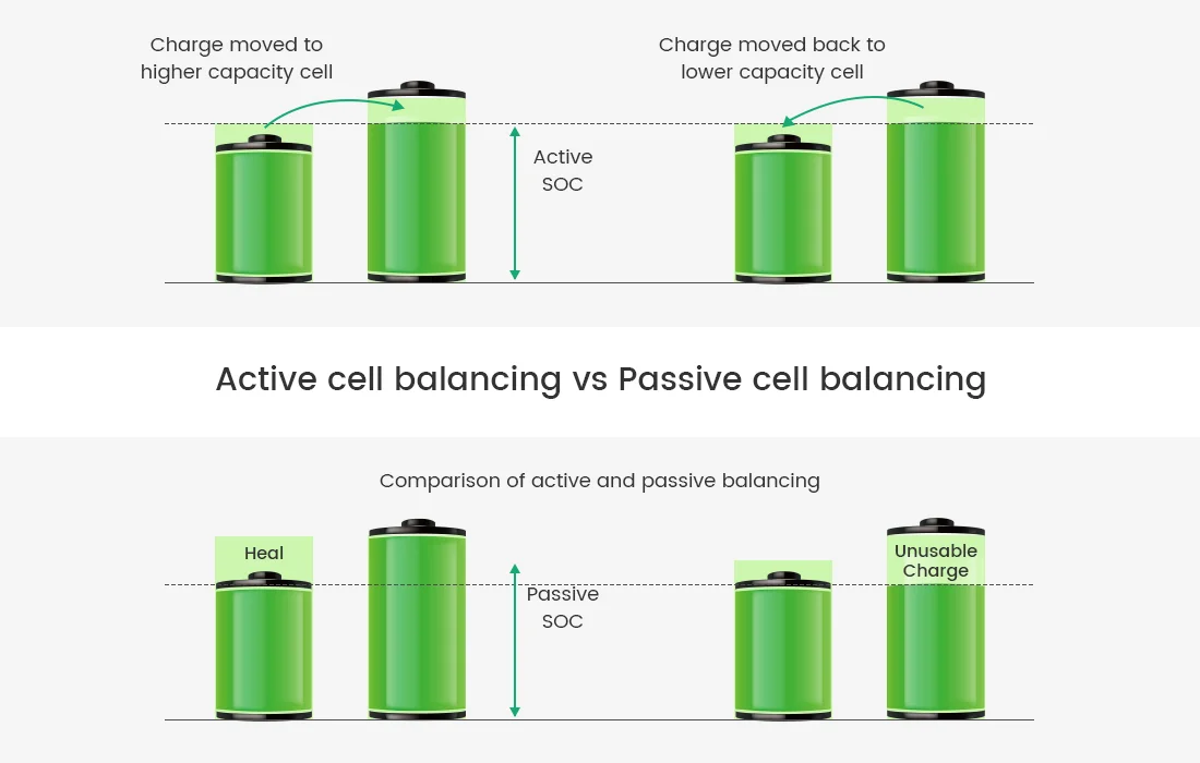
Hello! I am currently interested in creating an Active cell balancing system. For the Active cell balancing model, I intend to use the Resonant Switched Capacitor method. To implement this method, I plan to use an SG3525 PWM controller Module to apply PWM. I aimed to boost the 5V output from an Arduino to 10V using a Boost converter and then operate the SG3525 to obtain a 5V PWM signal. However, after connecting a resistor and measuring the output voltage of the SG3525, I found it to be a low 2.8V, which makes it difficult to drive a Mosfet. According to the description of the SG3525 PWM controller Module, it should output 5V, but I am unsure why only 2.8V is being produced. I would like to know why this is happening and how to solve this issue. Thank you.
ps. I used 330koms and 10kHz, 50%duty cycle
 

Attachments

  • KakaoTalk_20240509_221323957.jpg
    KakaoTalk_20240509_221323957.jpg
    2.3 MB · Views: 28
  • KakaoTalk_20240509_221323957_01.jpg
    KakaoTalk_20240509_221323957_01.jpg
    1.4 MB · Views: 26
  • KakaoTalk_20240509_221323957_02.jpg
    KakaoTalk_20240509_221323957_02.jpg
    1.4 MB · Views: 29
To get 5V output, you'll supply about 5.5 - 6V to SG3525 Vc pin. Apparently actual Vc voltage is too low.

We don't know which modules you are using and how they connect Vc.
 
Use KVL to determine your impedances and cause for loss in voltage.
1715271388521.png

Vcc must be 8V min. or as you defined 10V
Loads must be defined and compared with source impedance.
1715269473092.png

Active battery balance is an old patent recently revived by new Chinese and Korean papers that try to increase the 0% efficiency of passive BMS systems to 80~95% efficient in the 0.5~2W region during power transfer to next series cells. This replies on low ESR, ESL and RdsOn, Coss series resonance switching and thus the boost regulator must also transform those impedances backwards from lower source at one half to as source reflected load of one quarter the net low Rs at resonance.

To determine the driver impedance compute the nominal slope on the VI curve, although given for a Vcc=20V, I believe this may affect current limits more than impedance. Then compare this with your load impedance from Ciss or Cin & Rg and voltage level to FETs.

Also examine this for 20V;

(Vcc-Voh)/ Io = Zo For high level, 3V/100mA = 30 ohms seems high and 2V/20 mA = 100 Ohms is worse. What do you expect at 8V? 5V?

I think we need more details on your design specs.


1715267062332.png


Your problem stems from this impedance transformation with a lot of unknowns and obviously too high a resistor. You can't just stick in any Boost regulator board and expect it to work. Try a lower Voltage 8V which is minimum but this concept of yours also suffers the loss from 8 to 5V when driving FET gate capacitance with transient current. You might want to consider low threshold (Vt=Vbat/2) SiC FETs instead without shootthru thus using Vbat for Vgs on half bridge
--- Updated ---

The latest I see is a CLLC converter is used to transfer the charge at resonant frequencies to achieve
zero-voltage zero-current switching (ZVZCS) for all the switches and diodes. One paper reports charge transfer is 89.4%, and the balancing efficiency is 96.3%.

Although the authors fallaciously conflate the quantity of switches reduction by 50% with the more important factor of cost as all switch impedance or costs do not have linear metrics or equal ratios, it is a good paper although the realization is obfuscated with block diagrams. I suspect the patent expired.
--- Updated ---

Not an answer but for those who want to learn there are many types of BMS systems, active buck-boost, chemical, active depending on requirements.
This is a good summary.

Although their "lossless switched Capacitor Matrix" is not as lossless as they say since all batteries and capacitors have ESR losses and with MPT that means 50% efficient so they must use much less than MPT for charge balance.
 

Attachments

  • 1715266737714.png
    1715266737714.png
    322.8 KB · Views: 22
Last edited:
5V supply won't get you out of UVLO.

Look into more modern PMICs in CMOS that can drive logic-level MOSFETs and like 5V input (POL DC-DC). ONSemi, TI, ST, et al, use disti selector tools?
 
At such a low frequency, seems like you could let the micro
execute any PWM and drive a basic MOSFET driver from a
logic output pin.

There are isolating MOSFET drivers now which might offer
some interconnection possibilities (like any-to-any cell
leveling) used with a FET or just for their low-Ron switch
and isolation qualities. Not super cheap though.
 

LaTeX Commands Quick-Menu:

Part and Inventory Search

Welcome to EDABoard.com

Sponsor

Back
Top