Continue to Site

Welcome to EDAboard.com

Welcome to our site! EDAboard.com is an international Electronics Discussion Forum focused on EDA software, circuits, schematics, books, theory, papers, asic, pld, 8051, DSP, Network, RF, Analog Design, PCB, Service Manuals... and a whole lot more! To participate you need to register. Registration is free. Click here to register now.

How to make an fast Analog Switch?

Status
Not open for further replies.
Most simulator models do not cater for reverse breakdown between c-e terminals.
When the c-e terminal is reversed biased it will break down at about 8 V with b-e forward biased or open. With b-e shorted it is down to around 0.7 V as expected. So in a real circuit, you will have unexpected results due to this breakdown.
True. The 2N3904 model used in LTSpice models in good agreement with your findings when the base is shorted with the emitter. Vec breakdown is about 0.65mV.
Due to the breakdown post #16 works.

With BE forward biased, it is not accurate at all.
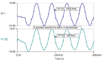
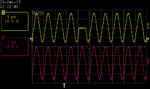
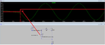
Post #18 does not get into the reverse active region at high load resistance, but as you decrease it, it gets however. (I do not use a negative pulse, see picture).
It shows that the transistor is still saturated (BE>0 and BC>BE>0) and conducts from emitter to collector. BE junction voltage is constant at about ~1.2V.
Because of that not modelling inaccuracy, shows impossible and inaccurate things.
 

Attachments

  • Pulse.png
    Pulse.png
    70.6 KB · Views: 83
Last edited:

With BE forward biased, it is not accurate at all.

That is why it is important to verify simulator predictions with actual measurements.

Update:

I tested it at 1 MHz since my lab amp capable of this large amplitude has a 1 MHz bandwidth.
 

Attachments

  • break_CE.png
    break_CE.png
    18.2 KB · Views: 88
  • break_CE_meas.png
    break_CE_meas.png
    17.2 KB · Views: 81
  • Like
Reactions: CataM

    CataM

    Points: 2
    Helpful Answer Positive Rating
Lastly the plot with 1 k as output load. The simulation results showed a reduction in output distortion, while the actual results look as bad as with the 330 ohm load.
 

Attachments

  • break_CE_meas330_1k.png
    break_CE_meas330_1k.png
    29.6 KB · Views: 82
  • Like
Reactions: CataM

    CataM

    Points: 2
    Helpful Answer Positive Rating
At least the model you are using in TINA TI models a bit the reverse breakdown of CE when BE is biased.
Measurements are in good agreement with your findings of post #20. :thumbsup:
 
Last edited:

At least the model you are using in TINA TI models a bit the reverse breakdown of CE when BE is biased.
No, the more accurate results were only obtained after I modified the TINA model to include reverse breakdown.
 
  • Like
Reactions: CataM

    CataM

    Points: 2
    Helpful Answer Positive Rating
I managed to set up a floating pulse generator to test my initial proposal. It gave very good results at 1 MHz as shown. I am unable to do tests at 10 MHz at the moment.

The distortion due to the diodes in the bridge marked by yellow circles agrees with the simulation. The positive going edge of the initial pulse is shown by the arrow. There is a short dip as the transistor (2N3904) turns on.

It is also possible to gate-out any part of the waveform which may be handy in some applications.
 

Attachments

  • switch_330.png
    switch_330.png
    12.8 KB · Views: 101
  • plse_gate.png
    plse_gate.png
    8.8 KB · Views: 97

In the image called "plse_gate", where did you start turning it off ? I presume you needed a lot more negative bias than those 3 V you showed in your simulation, isn't it ?
 

The Tek AWG2041 pulse gen that I floated, only has a 2 Vpp maximum output into 50 ohm, so there is not a lot of negative offset to play with. I don't think at 1 MHz it is that critical.
At 10 MHz, it may be an issue where any delays and recovery times will have a large impact.

It will be interesting to know where the OP gets a 10 MHz @ 40 Vpp from?
I can generate 1 MHz @ 40 Vpp or up to 100 kHz @ 1 kVpp, but nothing that can do 10 MHz at 40 Vpp. Maybe he is using some kind of ham linear amplifier.
 

Attachments

  • plse_gen.jpg
    plse_gen.jpg
    48.3 KB · Views: 83
  • Like
Reactions: CataM

    CataM

    Points: 2
    Helpful Answer Positive Rating
Status
Not open for further replies.

Part and Inventory Search

Welcome to EDABoard.com

Sponsor

Back
Top