Continue to Site

Welcome to EDAboard.com

Welcome to our site! EDAboard.com is an international Electronics Discussion Forum focused on EDA software, circuits, schematics, books, theory, papers, asic, pld, 8051, DSP, Network, RF, Analog Design, PCB, Service Manuals... and a whole lot more! To participate you need to register. Registration is free. Click here to register now.

How to make a stepper work in closed loop

Status
Not open for further replies.

ishailesh

Junior Member level 3
Joined
Apr 4, 2012
Messages
31
Helped
6
Reputation
12
Reaction score
6
Trophy points
1,288
Location
New Delhi, India
Activity points
1,652
Hey all!
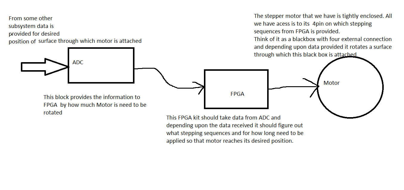
I am driving a stepper motor through FPGA ( Xilinx Virtex 2 Pro Board)
Here i have given some stepping sequences to it and it keep on running continuously.
Now i want that it should take some digital data and depending upon the data received it should rotate to some degree and stop.
Basically the idea is to make it work in a closed loop.
Please guide on the same how it can be achieved.
 

Re: Stepper in Closed Loop

The beauty of a step motor is that you really don't have to run it closed loop. So for your system, you just need to give your motor a specific number of pulses based on some input value. For example, if you have a 1.8 degree/per step motor and your input requires you to move 36 degrees, you just give your motor 20 pulses.

The OP probably really didn't mean closed loop but it can be done. Any 20 pulses will work if they are slow enough but then you are in start-stop-start-stop.. mode. You want to figure out the optimum time to deliver the second pulse so that it hits just before the motor begins to slow down. Then do the same for the third pulse which will be even sooner because the second pulse hits when the motor was already moving as opposed to a dead stop when the first one hit. The optimum time sequence will depend alot on the characteristics of the load.

So unless you want to do a whole lot of high level modeling you attach a position encoder to the shaft and you use that feedback to hand optimize your step table increments. Once you have it working you remove the encoder and it will work as long as your load doesn't change.
 

Re: Stepper in Closed Loop

Actually, the OP DID SAY that he wanted to move a certain number of degrees and stop, based on some input data. I think you are overly complicating this. Run it at the maximum allowable step rate and be done with it. Unless there are unstated requirements for ramping, etc. there's no need to over-engineer this.
 
  • Like
Reactions: PA3040 and FvM

    FvM

    Points: 2
    Helpful Answer Positive Rating

    PA3040

    Points: 2
    Helpful Answer Positive Rating
Re: Stepper in Closed Loop

The beauty of a step motor is that you really don't have to run it closed loop. So for your system, you just need to give your motor a specific number of pulses based on some input value. For example, if you have a 1.8 degree/per step motor and your input requires you to move 36 degrees, you just give your motor 20 pulses.

Well that's true for sure. But please take a look at problem in hand.


Here FPGA should take data automatically from ADC and depending upon the data received it should provide the required number of pulses to the MOTOR and all this run continously that is it would keep on getting data from ADC at some rate and every time data it receives from ADC it should perform the desired operation.
If it would have been one time operation then it could have been done by giving it some number ( 10,20 or as the requirement is ) of pulses. But its not that way.
I couldn't figure out how can i make this work.
Please help me in same.
Thanks and Regards
 

Re: Stepper in Closed Loop

So in order to operate this as a loop you simply need to keep a count on the FPGA. If you were to constantly read the ADC, which the FPGA will do since it executes concurrently and continuously, then the stepper motor would be driven at all times. To fix this, look at your data rate and figure out how often a second you are actually reading samples from the ADC. Once you know this, then you can set a count so that the FPGA only sends out a stepper pulse once the timer expires, since you know that you have now received new data. I would also use a flag (just a std_logic_vector) that you toggle each time you receive new data; this will help you make sure that you don't accidentally send out a new stepper pulse just because the timer expired, but that you have actually received new data.

Regards,
Willis
 

This is still not quite clear what you are trying to do. Are you trying to control position? speed? angle? The way you originally presented this, you wanted to move a given number of degrees based on an some input. Now it's starting to sound like it's more complex, and you are trying to implement some closed-loop control. Is that true? If so then you will need some kind of controller in your FPGA (PID, for example).

Your diagram shows an open-loop system, but I suspect it's not.

I am trying to control the position and angle of a surface which is attached with Stepper Motor as like in Goniometers.
How using PID this can be achieved??
Yes it indeed works in closed loop.There are some more blocks in the system.(Position of the surface will provide some stimuli to those blocks and in this way these blocks will calculate the error signal and asked some desired changes in the position of surface making it work in closed loop)
I already have a feedback mechanism so i don't think PID will fit in picture.
So please help.
 

Ah, so the input to FPGA shown in your diagram is the error signal? Since you want continuous control (I think) then your PID controller would be inserted after the error signal. If you don't know anything about control loops, you need to study that a bit.

What I think you were initially proposing was a system that would generate an error signal (in units of steps); and then move the step motor. Then, after the motor completed its move, you would determine your new error and so forth. This COULD work, but it depends on what your REALLY are trying to do. I suspect this is not what you have in mind.
 

It seems like you know about the general operation of a closed loop control system, so it's not quite clear what you are missing? If "position and angle" are two "process values", there will be a problem to control them independently with a single "manipulated value". In any case, you must be able to specify an unequivocal error quantity that tells how to correct the motor position.
 

Ah, so the input to FPGA shown in your diagram is the error signal? Since you want continuous control (I think) then your PID controller would be inserted after the error signal. If you don't know anything about control loops, you need to study that a bit.

What I think you were initially proposing was a system that would generate an error signal (in units of steps); and then move the step motor. Then, after the motor completed its move, you would determine your new error and so forth. This COULD work, but it depends on what your REALLY are trying to do. I suspect this is not what you have in mind.

Hey I did take at a look at control loops. PID controller works when you have a set point as well as a measured process variable.
It works by minimising the error between two. The control block takes the error signal i.e. difference between set point and measured point.
But in my case its not that way.
I am rotating stepper motor which in turn change the position and angle of a surface.(Position of the surface will provide some stimuli to other blocks and in this way these blocks will calculate some value which tells to FPGA for new position of surface) So i don't think i can employ PID controllers here.
So please help so that it could work without manual intervention.
FPGA should take the "ERROR SIGNAL" and calculate some "VALUE" so that surface moves to desired position and all it should work continously.
Please tell how it all can be done.

- - - Updated - - -

It seems like you know about the general operation of a closed loop control system, so it's not quite clear what you are missing? If "position and angle" are two "process values", there will be a problem to control them independently with a single "manipulated value". In any case, you must be able to specify an unequivocal error quantity that tells how to correct the motor position.

Yes position and angle are two seperate variable.The surface that is attached to my stepper motor has two direction of freedom.
Position and Angle of surface provide stimuli to other blocks which perform some operation and check whether desired position is achieved or not.
They provide an analog signal ("ERROR SIGNAL"). I am using 12 bit ADC.Now this 12 bit information needs to be manipulated so that required no. of pulses can be given to stepper. I dont really know how can i calculate that desired no. of pulses.

Please take a look at my code.

Here is the main code.


Code VHDL - [expand]
1
2
3
4
5
6
7
8
9
10
11
12
13
14
15
16
17
18
19
20
21
22
23
24
25
26
27
28
29
30
31
32
33
34
35
36
37
38
39
40
41
42
43
44
45
46
47
48
49
50
51
52
53
54
55
56
57
58
59
60
61
62
63
64
65
66
67
68
69
70
71
72
73
74
75
76
77
78
79
80
81
82
83
84
85
86
87
88
89
90
91
92
93
94
95
96
97
98
99
100
101
102
103
104
105
106
107
108
109
110
111
112
113
114
115
116
117
118
119
120
121
122
123
124
125
126
127
128
129
130
131
132
133
134
135
136
137
138
139
140
141
142
library ieee;
use ieee.std_logic_1164.all;
 
entity motor_state is
 
    port(
    
        en   : in   std_logic;
        clk     : in    std_logic;
        dir     : in    std_logic;
        reset       : in    std_logic;
        data_out     : out std_logic_vector(3 downto 0):="1111"
    );
    
end entity;
 
architecture motor_state_sequential of motor_state is
 
    -- Build an enumerated type for the state machine
    type state_type is (s0, s1, s2, s3);
    
    -- Register to hold the current state
    signal state   : state_type;
    signal clk_dv  :std_logic;
    signal clk_dv_final :std_logic;
    
    --Component declaration DCM
    
    COMPONENT dcm_divider
 
 PORT(
      CLKIN_IN : IN std_logic;
      RST_IN : IN std_logic; 
      CLKDV_OUT : OUT std_logic;
      CLKIN_IBUFG_OUT : OUT std_logic;
      CLK0_OUT : OUT std_logic
);
END COMPONENT;
 
COMPONENT clk_divider
 
PORT(
      CLKIN : IN std_logic;
        RST:in std_logic;
        ENABLE:in std_logic;
      CLKDV : OUT std_logic
);
END COMPONENT;
    
begin
 
Inst_trial1: dcm_divider PORT MAP(
CLKIN_IN => clk ,
RST_IN => reset,
CLKDV_OUT => clk_dv ,
CLKIN_IBUFG_OUT => open,
CLK0_OUT => open 
);
 
 
Inst_trial2: clk_divider PORT MAP(
CLKIN => clk_dv ,
ENABLE => en ,
RST => reset ,
CLKDV => clk_dv_final
);
 
    -- Logic to advance to the next state
    process (clk_dv_final, reset)
    begin
    if (en = '1')then
        if reset = '1' then
        state <= s0;
           elsif (clk_dv_final'event and clk_dv_final='1') then
            case state is
                when s0=>
                    if dir = '1' then
                        state <= s1;
                    else
                        state <= s3;
                    end if;
                when s1=>
                    if dir = '1' then
                        state <= s2;
                    else
                        state <= s0;
                    end if;
                when s2=>
                    if dir = '1' then
                        state <= s3;
                    else
                        state <= s1;
                    end if;
                when s3 =>
                    if dir = '1' then
                        state <= s0;
                    else
                        state <= s2;
                    end if;
            end case;
        end if;
    end if;
    
    end process;
    
    -- Output depends on the current state
    process (state)
    begin
     
if (en = '1')then
            case state is
            when s0 =>
                data_out <= "0001";
                for delay_counter1 in 1 to 2500 loop
                  for delay_counter2 in 1 to 2500 loop
                 end loop;
              end loop;
            when s1 =>
                data_out <= "0100";
                for delay_counter1 in 1 to 2500 loop
                  for delay_counter2 in 1 to 2500 loop
                 end loop;
              end loop;
            when s2 =>
                data_out <= "0010";
                for delay_counter1 in 1 to 2500 loop
                  for delay_counter2 in 1 to 2500 loop
                 end loop;
              end loop;
              
            when s3 =>
                data_out <= "1000";
                for delay_counter1 in 1 to 2500 loop
                  for delay_counter2 in 1 to 2500 loop
                 end loop;
              end loop;
        end case;
end if;     
    
    end process;
    
end motor_state_sequential;


The two blocks for dcm_divider and clk_divider are also there. But i am not pasting them here as they are just for clock division purpose.
Through this code i am able to drive the stepper motor. It is running continously.
So can you tell how can i make it move to some place and then stop instead of running continously.(Like what modification needs to be done in code)

There is one more thing.
Each time i have to use DIP switches to stop the motor or to change its direction.
( Can this be done through a keyboard ((((lets say pressing key "f" moves it forward and pressing key "b" moves it backword while pressing key "s" stops it)))))
((((simply saying how can i control the fpga using keyboard?????))))
Any idea???

Please help.
Thanks and Regards
 
Last edited:

Your code generates the step motor control pattern, that's a necessary but rather trivial part of the intended controller.

Either if you think that a PID matches your requirements or not, you'll need to define a control algorithm that calculates the next motor position depending on the measred process values and previos motor positions.

I have written code for a PID controller but i dont think it will match my requirements.
Here is the code anyway.


Code VHDL - [expand]
1
2
3
4
5
6
7
8
9
10
11
12
13
14
15
16
17
18
19
20
21
22
23
24
25
26
27
28
29
30
31
32
33
34
35
36
37
38
39
40
41
42
43
44
45
46
47
48
49
library IEEE;
use IEEE.STD_LOGIC_1164.ALL;
use IEEE.STD_LOGIC_ARITH.ALL;
use IEEE.STD_LOGIC_UNSIGNED.ALL;
 
---- Uncomment the following library declaration if instantiating
---- any Xilinx primitives in this code.
--library UNISIM;
--use UNISIM.VComponents.all;
 
entity PID_controller is
    Port ( error_in : in  STD_LOGIC_VECTOR (15 downto 0);
           control_signal_out : out  STD_LOGIC_VECTOR (15 downto 0);
           reset_pid : in  STD_LOGIC;
           clk_pid : in  STD_LOGIC);
end PID_controller;
 
architecture Behavioral of PID_controller is


signal control_signal: std_logic_vector(15 downto 0);
signal control_signal_previous : std_logic_vector( 15 downto 0);
signal error_signal_previous1: std_logic_vector( 15 downto 0);
signal error_signal_previous2: std_logic_vector( 15 downto 0);
 
 
constant proportional_multiplier: std_logic_vector( 6 downto 0 ):="1101011";
constant integral_muliplier:std_logic_vector( 6 downto 0):="1101000";
constant derivative_multiplier: std_logic_vector( 6 downto 0) :="0000010";
 
begin
 
process( clk_pid)
  begin
            if reset ='1' then
            control_signal_previous <="0000000000000000";
            error_signal_previous1<="0000000000000000";
            error_signal_previous2<="0000000000000000";
elsif (clk_pid'event and clk_pid='1') then
error_signal_previous2<=error_signal_previous1;
error_signal_previous1<=error_in;
control_signal_previous1<=control_signal;
control_signal<=control_signal_previous + ((proportional_multiplier + integral_muliplier + derivative_multiplier) * error_in) - ((proportional_multiplier + (2 *derivative_multiplier)) * error_signal_previous1 ) + ( error_signal_previous2 * derivative_multiplier);
control_signal_out<=control_signal;
end if;
end if;
end process;
end Behavioral;


Can you provide me any details on how can i control the FPGA using keyboards as stated in earlier post.
I am planning to make a GUI as well.
That shows what button was pressesd and in which direction motor is going to rotate.
If possible i would like to have control from my GUI as well as keyboard.
I also wonder if i can add a control so that i can specify by how much motor should rotate.

Thanks and Regards
 

Seems like post #4 answered the question.

Hey please take a look at the code and tell why i am unable to control the precise position of stepper.
It keeps on running.
I want that depending upon the data received through UART it should rotate to a precise degree.

Code:
#include "xparameters.h"
#include "xgpio.h"
#include "stdio.h"
#include "xstatus.h"
#include "xuartlite_l.h"
#include "xgpio_l.h"
#include "xuartlite.h"
#include "xbasic_types.h"
#include "xio.h"


#define XPAR_LEDS_4BIT_DEVICE_ID 0
#define XPAR_MOTOR_DEVICE_ID 2
#define XPAR_FORWARD_DEVICE_ID 1
#define XPAR_BACKWARD_DEVICE_ID 3
#define XPAR_XPS_UARTLITE_0_DEVICE_ID 1

XGpio GpioOutput_Led;
XGpio GpioOutput_sequence;
XGpio forward;
XGpio backward;
void init();
void delay()
{
   int k,p;
 for(k=0;k<150;k++)
    {
	   for(p=0;p<k;p++)
		  {
		   }
		}
}

void init()
{ 
  XGpio_Initialize(&GpioOutput_Led,XPAR_LEDS_4BIT_DEVICE_ID);
  XGpio_Initialize(&GpioOutput_sequence,XPAR_MOTOR_DEVICE_ID);
  XGpio_Initialize(&forward,XPAR_FORWARD_DEVICE_ID);
  XGpio_Initialize(&backward,XPAR_BACKWARD_DEVICE_ID);
  XGpio_SetDataDirection(&GpioOutput_Led,1,0x0);
  XGpio_SetDataDirection(&GpioOutput_sequence,1,0x0);
  XGpio_SetDataDirection(&forward,1, 0x1);
  XGpio_SetDataDirection(&backward,1, 0x1);
  XGpio_mSetDataReg(XPAR_MOTOR_BASEADDR, 1 , 0xf);
 
}

int main(void)
{
   init();
   Xuint8 read,read2;
   Xuint16 data;
   
	while(1)
	
	{
data = XUartLite_RecvByte(XPAR_UARTLITE_0_BASEADDR);
XUartLite_SendByte(XPAR_UARTLITE_0_BASEADDR, 0xff);


  //decide in which direction motor needs to rotate
	read = data / 127 ; 
 
 //decide by how much motor need to rotate.   

	read2 = data % 127;
	
//read = XGpio_mGetDataReg(XPAR_FORWARD_BASEADDR , 1);
//read2 = XGpio_mGetDataReg(XPAR_BACKWARD_BASEADDR, 1);
// if (read == 0x0 && read2 == 0x1) 
	
while (read2)
	
     {

 read2 = read2 - 1;

if (read == 0x0 ) 	
	   {
		  XGpio_mSetDataReg(XPAR_LEDS_4BIT_BASEADDR, 1 , 0xf);
		  XGpio_mSetDataReg(XPAR_MOTOR_BASEADDR, 1 , 0x1);
		  delay();
		  XGpio_mSetDataReg(XPAR_MOTOR_BASEADDR, 1 , 0x4);
		  delay();
		  XGpio_mSetDataReg(XPAR_MOTOR_BASEADDR, 1 , 0x2);
		  delay();
		  XGpio_mSetDataReg(XPAR_MOTOR_BASEADDR, 1 , 0x8);
		  delay();
		  }

// else if(read == 0x1 && read2 == 0x0)

else if ( read == 0x1 )
		  {
		  XGpio_mSetDataReg(XPAR_LEDS_4BIT_BASEADDR, 1 , 0xf);
		   XGpio_mSetDataReg(XPAR_MOTOR_BASEADDR, 1 , 0x8);
		   delay();
		   XGpio_mSetDataReg(XPAR_MOTOR_BASEADDR, 1 , 0x2);
		   delay();
		   XGpio_mSetDataReg(XPAR_MOTOR_BASEADDR, 1 , 0x4);
		   delay();
		   XGpio_mSetDataReg(XPAR_MOTOR_BASEADDR, 1 , 0x1);
		   delay();
			}
	else   
	    {
		 XGpio_mSetDataReg(XPAR_LEDS_4BIT_BASEADDR, 1 , 0x0);
		 XGpio_mSetDataReg(XPAR_MOTOR_BASEADDR, 1 , 0xf);
		 }
		 
 } 
 
  XGpio_mSetDataReg(XPAR_LEDS_4BIT_BASEADDR, 1 , 0x0);
  XGpio_mSetDataReg(XPAR_MOTOR_BASEADDR, 1 , 0xf);
  }

}

What wrong i am doing.
Please help.
 

What wrong i am doing.
Please help.

You're asking the wrong questions while providing the wrong information. You're welcome.

Oh wait. Help. Oh alright.

Include your testbench and screenshot of the results. That'll help us help you. You did testbench it, right?
 

The problem with stepper actuator is there is no defined initial condition of position.

For this reason all applications that require accurate angular position {or somehow converted to linear position} use optical interrupter method for defining "home " position. There are many types of one piece solutions for this with sensitivity of 0.2mm easily achieved.

This is used in all applications such as pick N place, screen printers, scanners, floppy disk drives etc.

This way if motor skips a step from accelerating too fast for the load, it can always be resync'd to home position.
 
  • Like
Reactions: FvM

    FvM

    Points: 2
    Helpful Answer Positive Rating
Status
Not open for further replies.

Part and Inventory Search

Welcome to EDABoard.com

Sponsor

Back
Top