Continue to Site

Welcome to EDAboard.com

Welcome to our site! EDAboard.com is an international Electronics Discussion Forum focused on EDA software, circuits, schematics, books, theory, papers, asic, pld, 8051, DSP, Network, RF, Analog Design, PCB, Service Manuals... and a whole lot more! To participate you need to register. Registration is free. Click here to register now.

[SOLVED] How to know whether pic16f876's oscillator is working ?

Status
Not open for further replies.

likhin

Newbie level 3
Joined
Nov 5, 2010
Messages
4
Helped
0
Reputation
0
Reaction score
0
Trophy points
1,281
Activity points
1,319
Hi all,

I am new to micro-controller programming. So I decided to start with a led blink program. My chip is 16f876A. I wrote an LED blink program, and it compiled successfully generating an hex file. And this code is working perfectly on a PIC simulator, but when I burnt it to hardware, nothing seems to work.
My assumption is that, the crystal oscillator is not working. How can I check whether the oscillator is working or not( With out using a CRO)? I meant, by measuring the OSC1 and OSC2 pin voltages? I am getting a voltage less than Vdd at OSC2 pin. Is that normal? Any help from u guys will be highly appreciated, as I am desperate to see my led blinking by a pic:smile:

Extra info:

Crystal frequency: 5Mhz
Vdd: 3v
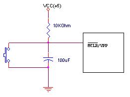
MCLR connected to VDD

compiler: CCS

code:
Code:
#include <16f876A.h>
#fuses HS,NOWDT,NOPROTECT,NOLVP
#use delay (clock = 5000000)

void main()
{

while(true){
output_high(PIN_C0);// tried all ports
delay_ms(500);
output_low(PIN_C0);
delay_ms(500);
   }
}
 

Check the MCLR Connection.
95_1200632863.jpg

Check for proper config setting.
Use 5Volt supply.
Replace the crystal and check. or Use RC Oscillator like the following to check:-

fig4-05.gif


Also check ground connection. Publish circuit

By the way, Have you configured those pins as output before make them high or low?
 
Last edited:

Check grounding capacitors are there for crystal oscillator.
Does 16F876 works with 3V supply ? check datasheet.
 

papunblg, thanks for ur reply. I have connected MCLR pin to vdd, and I tried RC oscillator also, with no success.

But I havent configured the pins as output, is it necessary to do so?. As far as I know, the built in function output_high(); will do it automatically. If not, can u tell how to configure a pin as output?

---------- Post added at 07:33 ---------- Previous post was at 07:28 ----------

Hi dinesh, thanks for ur reply. I have used grounding capacitor. But with no success. 16f876 can work with 3v. As per datasheet, it can work from 2v to 5v
 

Only the pic16LF876 works with 3V not the pic16F876... take note.
 

I do not use CCS compiler. Above are the general checking requirements for similar situations.

I found the following in CSS Inc's website:-

Automatic #fuses Configuration
The compiler configures some of the configuration bits (#fuses) for you automatically based upon your code:

•By default, the NOLVP fuse will be set (turn off low voltage programming)
•By default, the PUT fuse will be set (turn on the power-up timer)
•If there is no restart_wdt() in your code, it will set the NOWDT fuse. If there is a restart_wdt() fuse in your code then it will set the WDT fuse.
•The oscillator config bits will automatically be set based upon your #use delay() (see next section)
•If you have the debugger enabled in the PCW IDE, the DEBUG fuse will be set.
With the basic #fuses now being set automatically many programs will not need a #fuses directive.

This feature can be disabled by using the CCS3 backwards compatability (see previous section).


Try to run without the #fuse directive and with 5 volt supply and let me know the result.
 

Hi,

16F876 doesn't work with 3V, confirmed. carefully refer voltage Vs Oscillator speed graphs of 16F876 datasheet. It must be above 4V relevant to your Oscillator.

Thanks
 

Thanks for all u guys for your helping mind. Actually I find it myself that it wont work with 3V!. While trying all ways for solving the problem, I added another 1.5V cell to the already existing 2 cells. It just started working..!.( I already tried this with no result.But at that time, some other thing was missing I guess). I must say that, data-sheet for PIC16F876 is somewhat misleading for a beginner.
 

yeah! i lost a bet about a pic 16f working in 3V just by reading the first pages of the datasheet. that's how i know it...

Something relevant, in AVR there is also the same issue, two devices with different voltage range/max frequency, BUT in avr, you can make work a 5v micro with 3.3V even if it's out specs.


...

!!!

did you turned out the Browout Detect???????????? it's the main cause apart of the need of using HS instead of XT!!!!!!! try it one more time!
 

Status
Not open for further replies.

Similar threads

Part and Inventory Search

Welcome to EDABoard.com

Sponsor

Back
Top