Continue to Site

Welcome to EDAboard.com

Welcome to our site! EDAboard.com is an international Electronics Discussion Forum focused on EDA software, circuits, schematics, books, theory, papers, asic, pld, 8051, DSP, Network, RF, Analog Design, PCB, Service Manuals... and a whole lot more! To participate you need to register. Registration is free. Click here to register now.

how to interface MAX232 between two spi Devices?

Status
Not open for further replies.

dhakeparag81

Full Member level 2
Full Member level 2
Joined
Jun 6, 2012
Messages
142
Helped
1
Reputation
2
Reaction score
1
Trophy points
1,298
Location
INDIA
Visit site
Activity points
2,469
Hello there,

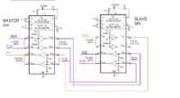
I want to add max 232 circuit between two spi devices.

these two spi device have relation master and slave

Is it possible?
or i have to add little more in the MAX 232 circuit?

thanx in advanced
 

hi dhakeparag81,
kindly explain little more about your actual requirement. We really dont have to add MAX232 circuit between two spi devices, because two SPI devices can be interfaced with having any extra circuitary.
 

hi vinoth8051,

i know that currently i have two spi devices working fine but i just want to increase the distance so i suppose it is a best way
by using MAX232 i increase the signal level up to certain extent
so i use the same devices which having pic 18f controller same the program, baud rate and other stuff i just adding two MAX232 ic's between them
 
Last edited:

Hi dhakeparag81,
SPI protocol uses single ended signalling. Due to noise susceptibility, range is limited to within the PCB Board only. MAX232 may not help here as it also uses single ended data transmission system. RS-485 protocol can be of help as it uses differential signaling, which are relatively less susceptible to induced noise. kindly refer the Application Report View attachment Extending SPI and McBSP With DIfferential Interface.pdf by Texa Instruements. It may help you better.
 

Yes, SPI normally runs at high speed, far faster than RS232 can manage. RS422 would be better, look at using MAX489s instead and twisted pair cable. If you really want to go SPI to SPI using an RS232 link, it would make more sense to use a pair of MAX3100 ICs and RS422 line drivers but you still wouldn't get as much speed as a direct connection.

Brian.
 

your right, wouldn't get as much speed as a direct connection but if i use max232 it increases the communication distance as compare to SPI
communication speed is not mandatory in my application but as you said max232 is slower it not supported in this requirement
 

If you are going to the trouble of using MAX232s and lowering the SPI clock speed, I would still suggest using MAX489s instead. They will work over much longer distances and at much higher speed and cost about the same.

Brian.
 

Hi dhakeparag81,

I'm not sure what is the required distance of your application, but I think you are trying to "reinvent the wheel". There are protocols for communicating over some distance and SPI is not one of them. why not using a simple UART or even better a power line communication method instead. If the units are already connected by a cable, then you can simply use the same wires for both communication and power transfer. It will save you some wires and simplify your application.
 

It's O.K. to suggest other solutions for the discussed problem, but we should be nevertheless able to tell under which conditions the circuit in post #5 works.

- Expectable MAX232 propagation delay (transmitter and receiver) is about 2.5 us, so the additional round trip delay (SCK to SDI) is about 5 us. Standard SPI setting tolerates up to 1/(2*fclk) delay, so SPI clock frequency must be clearly below 100 kHz to work with the MAX232 chain. By setting the receiver to late sampling, frequency can be increased to nearly 200 kHz. By changing to fast RS422/485 drivers/receivers, higher clock frequencies up to several MHz are feasible.

- Usually nCS is required for SPI synchronization, unless the slave has other synchronization means. nCS is apparently missing.
 

NOT CS ( - Chip Select). 'nCS' is the active low signal to select the device transferring or receiving the data.
SPI has three or four connections. nCS, data, clock and data in. Most also have a data output connection.

Brian.
 

Status
Not open for further replies.

Similar threads

Part and Inventory Search

Welcome to EDABoard.com

Sponsor

Back
Top