Continue to Site

Welcome to EDAboard.com

Welcome to our site! EDAboard.com is an international Electronics Discussion Forum focused on EDA software, circuits, schematics, books, theory, papers, asic, pld, 8051, DSP, Network, RF, Analog Design, PCB, Service Manuals... and a whole lot more! To participate you need to register. Registration is free. Click here to register now.

how to give port protection for micro controller??

Status
Not open for further replies.

skarthikshines

Member level 5
Joined
Feb 21, 2011
Messages
81
Helped
1
Reputation
2
Reaction score
1
Trophy points
1,288
Activity points
2,060
hi all.
am a beginneer for R&D DESIGN . am using MSP430 for my project so its contain fully 3.3 v operation.so here how can i give the port protection for my micro-controller. my analog in put voltage will be (0 to 10)v.. i searched in net and i gave the 3.3v zen er diode for port protection. but the problem is while i giving the 10 v for zener its getting drived for 3.2 v even so am getting 100mv error.. how can i solve this..and suggest me any other efficient port protection method ??
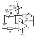
 

I think it is range extension problem that your facing ....if I understand correctly.....you want to have anlog voltage range of 0 to 10v and you want to have same range migrated to 0 to 3.3 v .....best thing is you can use opam design for that....if you want I can provide you range extension design using opamp....also in case of protection ..... your signal is almost double than voltage rating is MCU....in case of zinner burnout ....you may end up lossing you port pin.....My second recommendation is use potentail devide network ...that meight help you
 

Component failures possibility is every where, like Zener and some time Resistors network, too. I think the best possibility is left only the opamp, the failure will 90% save the connected MC as very rare see the opamp gets short cicuited (output to +ve supply rail). As suggested by milind resistors network will work (but to me) the temperature effect is there.
 

An opamp with the same power supply as the mcu would protect the pin since the output can not go over the power supply, you can use a voltage divider in the opemp input.

Another option used is connecting two Schottky diodes from the input pin to ground and Vcc, these will conduct is the input goes >Vcc+0.3v or lower than GND-0.3v, you also need a resistor at the input to limit the current if the diodes conduct.

Take a look at https://www.cirrus.com/en/pubs/appNote/an20.pdf

Alex
 

look first of all i think you must use a potential divider at the 10v side so that the voltage at lower resistor will be 3v when 10v is applied across the potential divider. that will do for the conversion.then for protection you may use a 3v zener parallel to lower resistance of potential divider. now the zener wont heat up because the top resistance will limit the current flow to it
 

I think it is range extension problem that your facing ....if I understand correctly.....you want to have anlog voltage range of 0 to 10v and you want to have same range migrated to 0 to 3.3 v .....best thing is you can use opam design for that....if you want I can provide you range extension design using opamp....also in case of protection ..... your signal is almost double than voltage rating is MCU....in case of zinner burnout ....you may end up lossing you port pin.....My second recommendation is use potentail devide network ...that meight help you
i tried with potential devider and with zener protection the problem is if am giving the 10v to the potetial divider means it divide the voltage proberly to 3.3v but if am connecting the zener at potential divder output means .. while i giving 10 v input its giving oly 3.210v at zener output.. so am getting the 0.080v error.. so kindly send me the opamp design with protection..
 

have you put the resistor exacty parallel to lower resistence.did you use a 3.3 zener or 3v zener. if you used 3v zener and then if it gave you 3.2v it means the current through the zener is more. in that case it will be better if you redesign the potential divider with higher value of top resistor.

if you want opamp based do an inverter unity gain and then an inverter amp with gain adjusted to get 3.3 at 10v peak input will be enough know.

---------- Post added at 11:29 ---------- Previous post was at 11:13 ----------

hey check this out and use the below equation to change resistance values to 10 input.....
 

i tried with potential devider and with zener protection the problem is if am giving the 10v to the potetial divider means it divide the voltage proberly to 3.3v but if am connecting the zener at potential divder output means .. while i giving 10 v input its giving oly 3.210v at zener output.. so am getting the 0.080v error.. so kindly send me the opamp design with protection..

Hi ,

I am atteching a design of the opamp....but you need to first tune the resistances value so that you get the 3v at the opamp output when apply 10 v input ....second ....please apply +/-12v for VCC operation ....you can derive also for the gain and linearity for this case Non_inverting_opamp.png
 

Hi ,

I am atteching a design of the opamp....but you need to first tune the resistances value so that you get the 3v at the opamp output when apply 10 v input ....second ....please apply +/-12v for VCC operation ....you can derive also for the gain and linearity for this case View attachment 64020
ok ok.. for protection what should i do..
 

- 11V TVS (transil) on input
- resistor divider + capacitor to GND (division and lowpass filter to reject high frequency noise)
- clamping shottky diodes to GND and VCC, preferably ultra-fast kind
 

hi all i added my circuit here have look and say the solution.. am giving 10v input its geeting proberly divide by potential divider and giving 3.3v output at before 100e but while i measuring near to zener it s giving oly 3.200 so am getting 0.100v error how can i rectify this problem??test.JPG
 
Last edited:

...while i measuring near to zener it s giving oly 3.200 so am getting 0.100v error how can i rectify this problem??**broken link removed**

Read again all the solutions that have been provided to you.
I don't understand why you insist on the zener solution.

Alex
 

Read again all the solutions that have been provided to you.
I don't understand why you insist on the zener solution.

Alex

hi all,
thanks for your suggestion as per your suggestion i made modification in my circuit kindly find the attachement.. and say your feed back ..whether this alone enough or any thing i should add with this circuittest.JPG
 

The clamping diodes should be connected to the mcu supply (3v3) and also use low Vf Schottky diodes like BAT85 (Vf about 0.3v).
The 1N4148 has a Vf about 0.7v (or higher) , you have used a 2.5v in the high side to compensate for that but your diode is probably already on with 3v3 (2.5v+0.7=3v3) and you don't want that, you want it to be on with a voltage higher that the usual operating input , like 3v3+0.3v=3.6v.

In addition your lower side diode can't protect the input because it will conduct with -0.7v which is a level beyond the min voltage for the pin, again a Schottky diode would limit this to -0.3v.

In any case there should be a resistor between the opamp output and the diodes to limit the current when they conduct.

Alex
hi as per your suggestion i added a series resistor between opamp and diod.. but during this case am getting the same problem which i faced earlier thts while i giving 10v input .. before 100 ohm am getting proberly 3.3v but after 100 ohm getting 3.177v oly so ..am geeting around 0.133v drop.. ?what shll i do now? i have attached that schematic..t1.JPG
 

hi as per your suggestion i added a series resistor between opamp and diod.. but during this case am getting the same problem which i faced earlier thts while i giving 10v input .. before 100 ohm am getting proberly 3.3v but after 100 ohm getting 3.177v oly so ..am geeting around 0.133v drop.. ?what shll i do now? i have attached that schematic..View attachment 64139

You selectively applied only one part of my suggestion.
I already said that you have to connect Schottky diodes and use the 3v3 supply.
 

You selectively applied only one part of my suggestion.
I already said that you have to connect Schottky diodes and use the 3v3 supply.
currently not having spice model for skoty diode thats y i did like that k i will try and get back to u...
 

From what I can tell you are using proteus, there are many available Schottky alternatives, for example BAT54
If you write Schottky in the component selector (also check show only parts with models) you will get a full list of the available models.

Alex
 

Status
Not open for further replies.

Part and Inventory Search

Welcome to EDABoard.com

Sponsor

Back
Top