Continue to Site

Welcome to EDAboard.com

Welcome to our site! EDAboard.com is an international Electronics Discussion Forum focused on EDA software, circuits, schematics, books, theory, papers, asic, pld, 8051, DSP, Network, RF, Analog Design, PCB, Service Manuals... and a whole lot more! To participate you need to register. Registration is free. Click here to register now.

How to find inductance of RFID multiturn Loop antenna

Status
Not open for further replies.

sr_raval

Advanced Member level 4
Joined
Jul 23, 2009
Messages
115
Helped
0
Reputation
0
Reaction score
0
Trophy points
1,296
Activity points
2,283
Dear All,

I have designed one RFID PCB loop antenna,how can i calculate the inductance of the antenna?i dont have LCR meter or any other measuring instruments,if i will get the inductance from that i can able to calculate total parallel capacitance,now how can i distribute this capacitance in to series and parallel capacitance,as per my circuit i have to solder series and parallel capacitance both,if you want any documents from my side i will give you....

Please help me.....
 

You'll find rules of thumb in RF handbooks and amateur radio literature. For complex geometries, e.g. PCB coils, I prefer a measurement or a numerical simulation. FastHenry from https://www.fastfieldsolvers.com is a good free tool.

You'll need a method to fine-tune the circuit after making it, so an oscilloscope and either a signal generator or the reader IC of the final design would be needed. It can be used also to measure the actual inductance by connecting a known capacitor. You don't need a LCR meter.
 

thank you for your valuable reply,what i want to know i will explain you by example.
say for example if i have total parallel capacitance 200pf,how can i distribute this value in to series and parallel capacitance,means what would be the series and parallel capacitor value?i am unable to download tool from the site you suggested.
 

I checked, that the site is working. Here's the direct tool's link:

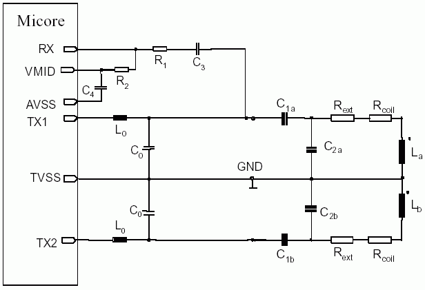
But the tool is for inductance calculation only, not for design of resonant circuits or filters. I guess, you intend a matching circuit like the below Philips/NXP application? Viewn from the coil, the parallel and series capacitors are simply added. Generally, the series capacitor is smaller by a factor of e.g. 10 to provide the impedance transformation, so the parallel capacitor mainly determines the resonance frequency.

72_1256981578.gif
 

I have this document but my confusion is as under
1) first find out the exact inductance and series resistance of the antenna,i don't have any measuring instrument
2)according to inductance i have to find the value of C1a,C1b,C2a and C2b
 

1) I suggested FastHenry, any of those high end EM simulators could also do, of course. As I previously mentioned,
I can hardly imagine to put the circuit in operation without measuring instruments. The usual RFID reader circuits are
high Q and most likely need fine tuning.

2) It's a RLC network, standard network theory applies. If you aren't motivated
to figure out the exact expressions, use an electronic circuit simulator to evaluate
the circuit behaviour.
 

which simulation tool you prefer?
 

Status
Not open for further replies.

Part and Inventory Search

Welcome to EDABoard.com

Sponsor

Back
Top