Alex Liao
Member level 4
Hi,
Giving the geometry, radius, width, and turns, the rough inductance(Lind) and quality factor(Qind) can be computed. This can be viewed from the property of a modelled Ind device (say, spiral_std_mu_z) in a given technology in the Cadence Schematic tool. By sweeping the geometry parameters, one can have the relationship between Qind and Lind like the attached plot (c).

As it is known that the inductor can be modelled in a parallel LC or Series LC network depending on its schematic.
Plot (a) and (b) also show that the Parallel (Rp) and Series Resistance (Rs) of this Ind can also be acquired.
1. I am wondering are there such parameters, Rs and Rp, which can be viewed directly in Cadence (given different geometry values or Lind values) like the Qind (directly from property of the inductor)?
[i.e., How to get or verify the resistance or reactance of a Inductor in Cadence ?]
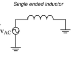
2. I also did an AC simulation with the test circuit as attached:

I have noticed I can view several resistance via result browser, instance parameter,
rs1_1, rs2_1 rs_3_sub, rx_2_3_sub with r(Ohm) field like, = 2.015.
Not sure if those are more or less related to what I want Rs or Rp.
Thanks,
Alex
Giving the geometry, radius, width, and turns, the rough inductance(Lind) and quality factor(Qind) can be computed. This can be viewed from the property of a modelled Ind device (say, spiral_std_mu_z) in a given technology in the Cadence Schematic tool. By sweeping the geometry parameters, one can have the relationship between Qind and Lind like the attached plot (c).

As it is known that the inductor can be modelled in a parallel LC or Series LC network depending on its schematic.
Plot (a) and (b) also show that the Parallel (Rp) and Series Resistance (Rs) of this Ind can also be acquired.
1. I am wondering are there such parameters, Rs and Rp, which can be viewed directly in Cadence (given different geometry values or Lind values) like the Qind (directly from property of the inductor)?
[i.e., How to get or verify the resistance or reactance of a Inductor in Cadence ?]
2. I also did an AC simulation with the test circuit as attached:

I have noticed I can view several resistance via result browser, instance parameter,
rs1_1, rs2_1 rs_3_sub, rx_2_3_sub with r(Ohm) field like, = 2.015.
Not sure if those are more or less related to what I want Rs or Rp.
Thanks,
Alex