Continue to Site

Welcome to EDAboard.com

Welcome to our site! EDAboard.com is an international Electronics Discussion Forum focused on EDA software, circuits, schematics, books, theory, papers, asic, pld, 8051, DSP, Network, RF, Analog Design, PCB, Service Manuals... and a whole lot more! To participate you need to register. Registration is free. Click here to register now.

[PIC] How to extract information from a varying signal on ADC input ?

Status
Not open for further replies.

muhibraza

Member level 1
Member level 1
Joined
Oct 11, 2010
Messages
38
Helped
3
Reputation
6
Reaction score
3
Trophy points
1,288
Visit site
Activity points
1,578
Hello,
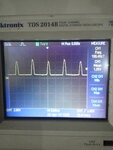
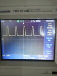
I have the following signal at adc channel 1 input of PIC18F26K22 Microcontroller:
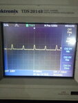
20140422_130711.jpg20140422_130759.jpg20140422_130826.jpg

now the problem is that I need to read only a dc value on which the varying signal is imposed upon. Like this
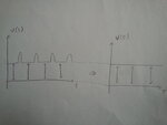
20140423_111736.jpg

So can anyone guide me what are the possible methods for getting this information out of the signal ? (hardware or software, any methods)

I think I can use a large value capacitor in parallel with the signal such that it would chop all the frequencies above 1 or 2 Hz.... but again, the output would be filtered but not to the desired value as I have shown, because the capacitor would charge up to the peak of this signal hence the original value would still not be achieved... Am I right ?

also please let me know if there is any software method for this for example taking many samples in one time period and then checking the rate of change (or the slope) and when the slope equals zero then we know the required value etc is this possible ? if yes then how ?
 

If you know the frequency of the peak appearing, then use a sample and hold circuit, and sample on the non-peak area.

hi sankar, the problem is that that signal changes its shape as the "non peak" area amplitude increases... for example if there is 10 ms total time period and 2 ms peak time, then it does not remain the same when the amplitude increases.... the peak time may become even longer so we can not be certain about when to sample...
see the waveforms here:
**broken link removed**
 

hello,


if you measure the derivee of signal: Delta Volt / delta T, you can remove the measure over a fixed threshold
so you only keep the average DC value
on the DC flat part of your signal DV/Dt=0 ...of very small
and different from 0 when amplitude increase or decrease rapidily.
 

hi paulfjujo,
Thanks for replying...

I used the slope method to detect the signal by taking 20 samples in every 10 ms span... then I subtracted every second sample from the first and saved the results... then I checked on which sample the difference is zero, there we get the zero slope and we get the signal value...
It worked fine for low voltages
but
on the high voltages the ADC skipped values and took large jumps.... this is because on the higher voltages the wave shape is such that the zero slope occurs twice in every cycle... check this image:
**broken link removed**

so because the zero slope occurs more than once therefore this method also fails :(

any other ideas ?
 

Hi,

you calculate a run low pass filtered signal: slp = slp + ( newADC - slp) / 200 ( this gives about 10Hz cutoff frequency with your 2000 Hz sampling frequency
(mind to use float or at least ADC_bits + 8)

For your desired value now use only ADCvalues that are <= slp AND have small |du/dt|.
I reccomend to low pass filter your desired value the same way as slp.

Hope this helps
Klaus

edit1: corrected filter calculation: 200 smpl/s --> 2ksmpl/s, 1Hz --> 10 Hz
 

hi KlausST,

I am sorry I could not understand what are you trying to say....
slp = slp + ( newADC - slp) / 200
how did you derive this formula for the 10 Hz cutoff frequency ?
yes I am using float variable to read the adc values... but I dont understand the formula please ellaborate more... Thank you
 

Take as many samples as possible. Check for a falling slope, ie. when a sample value is smaller than the preceding one. Then look for, say, 5 samples with the same value. That should give the DC baseline voltage.
 

Hi muhibraza

slp stands for: Signal LowPass filtered

Every time you get a new adc value the slp value needs to be updated. The first slp is the updated result.
The slp rightvof the "=" is the old value.
NewADC is the actual reading of your adc.

The formula acts like an R C lowpass filter.
Slp is the C voltage = lowpass filter output.
NewADC is the lowpass filter input
Therefore the value in brackets is the voltage across the resistor
And the "200" is the time constant of your filter.
As a guesstimate you can calculate with: time constant = value/samplerate
200 / 2000 Hz = 0.1 s

For a microcontroller it is easier to multiply than to devide, therefore you may multiply with 0.005 instead devide by 200.

Hope this helpes
Klaus
 

Status
Not open for further replies.

Similar threads

Part and Inventory Search

Welcome to EDABoard.com

Sponsor

Back
Top