eyeow
Junior Member level 1
After understanding the behavior of Peltier, now would like to find the best way improve the circuit design to drive the Peltier at desired voltage and current to protect the Peltier from damaged as well as the Peltier could do the cooling to a desired temperature with best cost-effective way.
Loading:
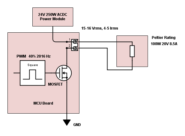
Peltier rating: 100W, Vmax 20V, Imax 8.5A. After some experiments, the desired input voltage is 15-16 V, expected current drawn will be 4-5 A.
Existing circuit Problem:
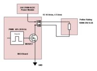
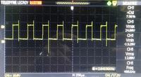
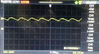
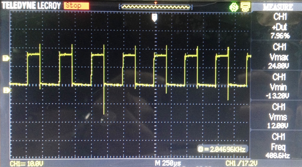
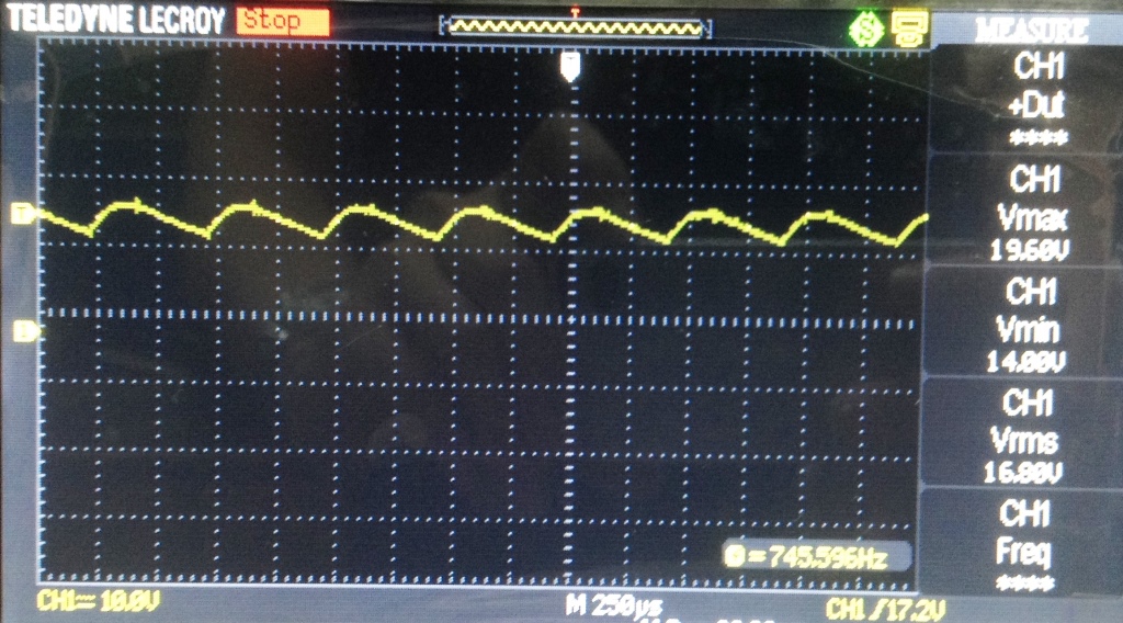
A microcontroller is used to output pwm signal to drive the mosfet as shown in the diagram. PWM setting duty cycle 40%, Freq 2016 Hz. DMM Voltage reading: 9.5 V, Clamp Meter Current reading: 3.14 A. The readings look ok. We can control the duty cycle to desired voltage level 15-16V. But based on scope measurement, the Vmax and Vin actually exceeds the Peltier operating voltage range as shown in the photo which we may think it will damage Peltier slowly.
Constraint/Condition:
At this moment we cannot lower the power module voltage rated output 24V.
We also don't have option to change to higher voltage rating Peltier due to cost issue.
Question/Solution:
1. we got this proposal 1 as below:
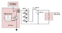
4 diodes + 4 heatsinks: To drop the 24V DC to 17-18 V and disipate heat
LC filter circuit: to filter and smooth spikes at Vmax and Vmin
It solves our problem and we can tune the duty cycle to get back desired voltage, as long as the diode stops the rated voltage at 17-18V, but those components take extra space, cost is higher to use 4 extra heatsinks to dissipate the diodes' heat and required fan as well. Inductor can be optional as Peltier is seems like a resistive loading only.
2. Voltage divider? High power rating resistors + heatsinks may be required, and it also limits the current as well, right?
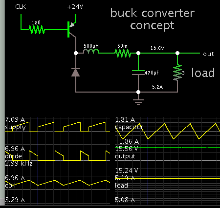
3. Buck DCDC Converter? Any good recommendation?
4. Other solution/ suggestion to improve existing PWM control/mosfet?
Thanks.
Loading:
Peltier rating: 100W, Vmax 20V, Imax 8.5A. After some experiments, the desired input voltage is 15-16 V, expected current drawn will be 4-5 A.
Existing circuit Problem:
A microcontroller is used to output pwm signal to drive the mosfet as shown in the diagram. PWM setting duty cycle 40%, Freq 2016 Hz. DMM Voltage reading: 9.5 V, Clamp Meter Current reading: 3.14 A. The readings look ok. We can control the duty cycle to desired voltage level 15-16V. But based on scope measurement, the Vmax and Vin actually exceeds the Peltier operating voltage range as shown in the photo which we may think it will damage Peltier slowly.
Constraint/Condition:
At this moment we cannot lower the power module voltage rated output 24V.
We also don't have option to change to higher voltage rating Peltier due to cost issue.
Question/Solution:
1. we got this proposal 1 as below:
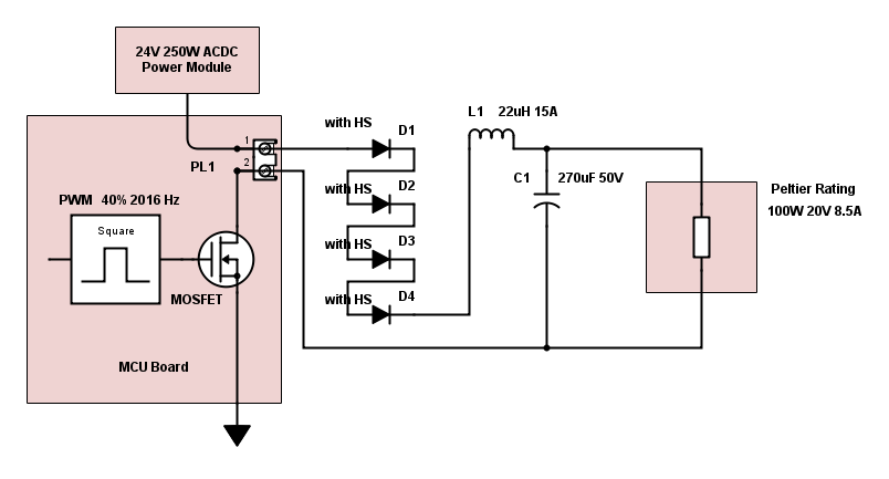
4 diodes + 4 heatsinks: To drop the 24V DC to 17-18 V and disipate heat
LC filter circuit: to filter and smooth spikes at Vmax and Vmin
It solves our problem and we can tune the duty cycle to get back desired voltage, as long as the diode stops the rated voltage at 17-18V, but those components take extra space, cost is higher to use 4 extra heatsinks to dissipate the diodes' heat and required fan as well. Inductor can be optional as Peltier is seems like a resistive loading only.
2. Voltage divider? High power rating resistors + heatsinks may be required, and it also limits the current as well, right?
3. Buck DCDC Converter? Any good recommendation?
4. Other solution/ suggestion to improve existing PWM control/mosfet?
Thanks.