Continue to Site

Welcome to EDAboard.com

Welcome to our site! EDAboard.com is an international Electronics Discussion Forum focused on EDA software, circuits, schematics, books, theory, papers, asic, pld, 8051, DSP, Network, RF, Analog Design, PCB, Service Manuals... and a whole lot more! To participate you need to register. Registration is free. Click here to register now.

how to design high voltage ultrasound circuit for therapy?

Status
Not open for further replies.

mrmalaysian

Newbie level 4
Newbie level 4
Joined
Jun 20, 2013
Messages
5
Helped
0
Reputation
0
Reaction score
0
Trophy points
1
Visit site
Activity points
36
Hi,
I need help to design circuit with output sinusoidal wave frequency 500kh-1Mhz, and Vpp-200V.
Basically, as far as know, the circuit should have an oscillator, amplifier and filter.
What circuit is the best for producing high freq?
Can I use 555 timer and freq doubler??
 

A 555 will give you a square wave, not a sine wave. I suppose you COULD put a filter on that , but I think you'd be better off just generating a sine wave and amplifying it.
 
I try using 555 timer and get the output square wave with 70khz freq,
Can u suggest me what type of circuit can generate sine wave of frequency 500khz and above?:?:
 

I try using 555 timer and get the output square wave with 70khz freq,
Can u suggest me what type of circuit can generate sine wave of frequency 500khz and above?:?:

First you should know specifications of the transducer. From them you can derive the specifictions of the generator. The 555 is not suitable for frequency > 100 kHz. Generating 200 V p-p is better done with vacuum tubes, available for old-timer audio amplifiers. Radio amateurs will know where to buy good vacuum tubes or the complete generator. Try e-bay or a similar channel.
There are good designs of ultrasonic jewel cleaners with power MOSFETs but such devices do not typically operate over 500-1000 kHz.
 
I see you want a variable frequency, is this so you can tune it to the transducer, or is the change of frequency part of the theraphy? If it is you will need to retune the output network because a circuit that produces 200 V economically at 500 KHZ, will not produce hardly anything at 1MHZ without retuning. If you want it truly broadband - no tuning, its possible but the costs will be times 10.
Frank
 
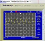
now i try to use crystal oscillator circuit and i get the output sinusoidal wave with freq 1Mhz.
Here i attach the circuit schematic and the output waveform.
The shape of sine wave looks not really smooth. Can someone help? How is that happen and how to improve it.?
oscillator cct1.pngresult_oscillator cct_1.5mhzcrystal.JPG
 

Apex Microtechnology (https://www.apexanalog.com) makes solid state, high voltage amplifiers in small hybrid modules suitable for driving piezos. They have some insanely fast parts with enormous slew rates. I used over 400 PA-95 parts with no problems. Worked as advertised. Lots of good design support for driving capacitive loads.

- - - Updated - - -

For easily variable and precise frequency with low distortion, have you considered using a DDS part (Direct Digital Synthesis)? How do you plan to control the frequency? With a manual control, local processor, remotely?
 
google 'crystal oscillator'

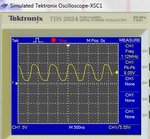
now i try to use crystal oscillator circuit and i get the output sinusoidal wave with freq 1Mhz.
Here i attach the circuit schematic and the output waveform.
The shape of sine wave looks not really smooth. Can someone help? How is that happen and how to improve it.?
oscillator cct1.pngresult_oscillator cct_1.5mhzcrystal.JPG
 

Why are posting this twice?

I don't believe that you need to worry about smaller waveform distortions in signal generation. You are presenting a rather complex oscillator circuit. Why this particular circuit? Do you understand what the purpose of each circuit detail is? If you do, you'll also know how to influence signal distortions.

But whatever the oscillator generated waveform is, it won't be exactly reproduced when passing the power amplifier.

Do you know the sensor's impedance characteristic of the sensor? It's an important information to design the power amplifier and output stage impedance matching.
 
You really must read post #6 and post #10, then you will start working more effectively to attain your target of getting 200V across some transducer of unknown type. That oscillator has twice the number of components in it then you need.
Frank
 
Status
Not open for further replies.

Similar threads

Part and Inventory Search

Welcome to EDABoard.com

Sponsor

Back
Top