Continue to Site

Welcome to EDAboard.com

Welcome to our site! EDAboard.com is an international Electronics Discussion Forum focused on EDA software, circuits, schematics, books, theory, papers, asic, pld, 8051, DSP, Network, RF, Analog Design, PCB, Service Manuals... and a whole lot more! To participate you need to register. Registration is free. Click here to register now.

how to design buck-boost converter?

Status
Not open for further replies.

hemnath

Advanced Member level 3
Joined
Jun 24, 2012
Messages
702
Helped
61
Reputation
120
Reaction score
57
Trophy points
1,308
Location
Chennai
Visit site
Activity points
6,589
i want to design +3 to 24V DC input voltage to fixed +5V DC using buck-boost. I don't have knowledge about that.
Please refer some good notes with simple explanation and please help me how to design this?

Thanks in advance :)
 

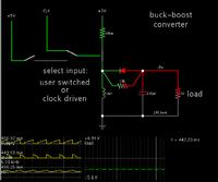
What helped me to grasp the principles of switched-coil converters was an animated, interactive simulator.

Below is a link to my conceptualization of a simple buck-boost.

Click it to open the falstad.com/circuit website, load my schematic, and run it on your computer. (Click Allow to load the Java applet.)

https://tinyurl.com/bwfxjou

Watch the scope traces. The coil is at the center of action.

You can change the load resistance as desired. Right-click on it and select Edit to bring up a window.

The power supply is 3V. You can change it to 24 V.

It lacks regulation. That requires additional circuitry.

Clock pulses are driving the switch.
You can choose to drive it yourself by clicking the switch in the middle.
Click the switch at left to start the switch-On cycle.
Let up on the switch to see the switch-Off cycle.

Continue at a pace that keeps 5V on the load at right.
You'll find that for a given supply V, there is a particular duty cycle that goes with it, to obtain 5V output at the load.

 
Status
Not open for further replies.

Part and Inventory Search

Welcome to EDABoard.com

Sponsor

Back
Top