Continue to Site

Welcome to EDAboard.com

Welcome to our site! EDAboard.com is an international Electronics Discussion Forum focused on EDA software, circuits, schematics, books, theory, papers, asic, pld, 8051, DSP, Network, RF, Analog Design, PCB, Service Manuals... and a whole lot more! To participate you need to register. Registration is free. Click here to register now.

How to define the voltage gain of a comparator?

Status
Not open for further replies.

fightshan

Junior Member level 3
Joined
Jul 30, 2013
Messages
28
Helped
0
Reputation
0
Reaction score
0
Trophy points
1
Location
China
Visit site
Activity points
260
When an opamp works as a compararor,to get a higher gain so as to reduce the non—ideal effect,the opamp is usually in open—loop mode ,my question is if we want to know the voltage gain ,the common mode voltage of the opamp must be defined first,however,the gain of opamp is decided by the common mode voltage ,and in the application of comparator ,the two inputs of the opamp are usually variating,so how to define the "common mode voltage" of a comparator?
This is a confusion to me ,as I can`t answer others "easy" question—— "what`s your comparator`s voltage gain?"
 

I don't understand what you mean by
the gain of opamp is decided by the common mode voltage
The common-mode voltage has little to do with the open-loop gain, at least within it's defined input common-mode voltage limits. Ideally it should have no effect.

A comparator's open-loop gain is defined the same as an op amp's open-loop gain. It's the change in output voltage divided by the input differential voltage change.
 

The common mode voltage rating of an opamp is a maximum type rating which has absolutely no relationship to its gain. It just sets the limits at the inputs over which the opamp functions properly. The common mode rejection ratio (CMRR) can and does set the limit for the opamp gain. A perfect opamp with its inputs tied together should have its output at zero volts, what ever the input voltage is. An opamp with a poor CMRR will have a spurious output voltage depending on the actual voltage of its tied together inputs. So if you used it as a comparator for two identical wave forms, there would be some output. So as the phase between the two sinewaves changed the output voltage would be a sine wave which never went to zero. If however you were comparing a sine wave to a DC level, then the CMRR would have the effect of changing the output DC level of the clipped sine wave by a small amount, because the DC bias level is common mode while the sine wave is differential mode.
Frank
 

I think the common—mode input voltage decide the DC operating point of an amplifier,diferent DC operating point will decide different Gm,so how can you tell "The common-mode voltage has little to do with the open-loop gain"?
 

I think the common—mode input voltage decide the DC operating point of an amplifier,diferent DC operating point will decide different Gm,so how can you tell "The common-mode voltage has little to do with the open-loop gain"?

The opamp is not a transistor.
In a transistor, the operating point (Ic) determines the transconductance gm and, thus, the gain.
However, the opamp is a voltage amplifier which is NOT characterized by any gm but by the open-loop gain Aol and - if any - the feedback network
But using an opamp as a comparator, there is another parameter which is important for you (because the opamp is operated without negative feedback): The input offset voltage.
Question: Do you know the effects connected with POSITIVE feedback (may be useful for comparator applications).
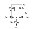
It is true that the opamp is not a transistor,but I think the ability to amplify small signals of an opamp comes from the gm of the transistor which determined by the DC operating point. In my circuit the comparator does not have any negative or positive feedback,let me take a simple amp for example:
a.png
now take the amp as a comparator,if comparing a sine wave to a DC level in Vin1 and Vin2,what the Vout will be?and how to answer the question"what is the voltage gain of the opamp in this comparator?"or "how to test the voltage gain of the opamp?"when we test the opamp,do we need define the common voltage?if need ,what is the common voltage?
 

Hi fightshan

From your schematic , the input comom mode range:
Vthn + vdsat1 + vdsat5 <= vin <= vdd + Vthn - (Vthp + vdsat3)

I know you mean if input op opamp lie outside the common mode range will decrease the gain because transistors are not in saturation
 

Hi fightshan

From your schematic , the input comom mode range:
Vthn + vdsat1 + vdsat5 <= vin <= vdd + Vthn - (Vthp + vdsat3)

I know you mean if input op opamp lie outside the common mode range will decrease the gain because transistors are not in saturation

I agree with you,but what`s your answer to my question?I have confusion.
 

It is true that the opamp is not a transistor,but I think the ability to amplify small signals of an opamp comes from the gm of the transistor which determined by the DC operating point. In my circuit
......now take the amp as a comparator,if comparing a sine wave to a DC level in Vin1 and Vin2,what the Vout will be?and how to answer the question"what is the voltage gain of the opamp in this comparator?"or "how to test the voltage gain of the opamp?"when we test the opamp,do we need define the common voltage?if need ,what is the common voltage?

1.) Yes - you are right, the overall gain depends on the gm of the transistors. However, the quiescent dc current within the opamp is fixed - and, hence. the gain is fixed.
2.) The open-loop voltage gain Aol of an opamp is frequency dependent and is specified in the corresponding data sheet. For comparator application it is the dc gain that matters.
3.) Test procedures for the open-loop gain can be found in data sheets or other opamp related papers (gain=Vout/Vin for a proper dc operating point: DC offset cancellation/compensation/reduction)
4.) For a differential amplifier (which is NOT an opamp) as shown in your post the CMMR is not as large as for operational amplifiers. Hence, the output VOLTAGE depends not only on the differential gain but also on the common mode gain resp. the common mode voltage. However, the diff. GAIN does not depend on common mode properties.
5.) "What is the common mode voltage"? In your first post you have mentioned the term "common mode" three times. I assume you know what you are speaking of.
 
  • Like
Reactions: fightshan

    fightshan

    Points: 2
    Helpful Answer Positive Rating
    V

    Points: 2
    Helpful Answer Positive Rating
Referring to post #6, you'll find a gain calculation in the text book from where you copied the amplifier circuit (Razavi or whatsoever). The transistor Id and respective gm is primarly set by the current source transistor M5 and only slightly depending on Vcm, as long as all transistors are in saturation.
 

Status
Not open for further replies.

Part and Inventory Search

Welcome to EDABoard.com

Sponsor

Back
Top