brandontran
Newbie
Hi Folks,
I'm not an expert with electronics but I hope experts can guide me in the right direction on what part is needed. I have a fan I like, the digital panel that is on it died. No big deal, I'll just take it apart and add an analog knob switch for 1, 2, 3 speeds or variable is fine as well. As I dug into this fan, I learn the complexity of brushless motors and that I can't just simply hook up power to it. So I then learned about how it has a controller and if I connect 2 wires the fan comes on full speed. I made a diagram of the 3 wires I'm working with. These wires came from the digital panel. I cut them and then touched the wires to see what they would do.
What components can I use to have a knob to turn that makes fan go slow, medium, fast or variable is fine as well? I learned that a potentiometer only varies resistance and tested with multimeter which was cool. I found a potentiometer and wired it up for kicks. Any pro would know that didn't do anything. The fan was full speed all the time.
So do I need to vary the voltage 1-4V to make the speed of the fan change via these control wires?
I'm curious if something like this would do the trick. Also not sure how to wire it up...
Thanks for any help.
I'm not an expert with electronics but I hope experts can guide me in the right direction on what part is needed. I have a fan I like, the digital panel that is on it died. No big deal, I'll just take it apart and add an analog knob switch for 1, 2, 3 speeds or variable is fine as well. As I dug into this fan, I learn the complexity of brushless motors and that I can't just simply hook up power to it. So I then learned about how it has a controller and if I connect 2 wires the fan comes on full speed. I made a diagram of the 3 wires I'm working with. These wires came from the digital panel. I cut them and then touched the wires to see what they would do.
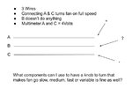
- I have 3 wires
- A is +
- B not sure what it is
- C is -
- These 3 wires were connected to the digital panel
- Connecting A and C makes the fan turn on full speed
- If I multimeter A and C I get 4 volts
- Motor is 24V DC Brushless and the controller is a black box to me right now.
What components can I use to have a knob to turn that makes fan go slow, medium, fast or variable is fine as well? I learned that a potentiometer only varies resistance and tested with multimeter which was cool. I found a potentiometer and wired it up for kicks. Any pro would know that didn't do anything. The fan was full speed all the time.
So do I need to vary the voltage 1-4V to make the speed of the fan change via these control wires?
I'm curious if something like this would do the trick. Also not sure how to wire it up...
Amazon.com: TeOhk XL4016E1 DC-DC Buck Converter Voltage Regulator DC4-40V 1.25-36V 8A 200W High Power Efficiency Step Down Converter Power Supply Module Efficiency Adjustable Buck: Electronics
Buy TeOhk XL4016E1 DC-DC Buck Converter Voltage Regulator DC4-40V 1.25-36V 8A 200W High Power Efficiency Step Down Converter Power Supply Module Efficiency Adjustable Buck: Power Converters - Amazon.com ✓ FREE DELIVERY possible on eligible purchases
www.amazon.com
Thanks for any help.