ibnul7
Newbie level 6

- Joined
- Aug 23, 2013
- Messages
- 11
- Helped
- 0
- Reputation
- 0
- Reaction score
- 0
- Trophy points
- 1
- Activity points
- 95
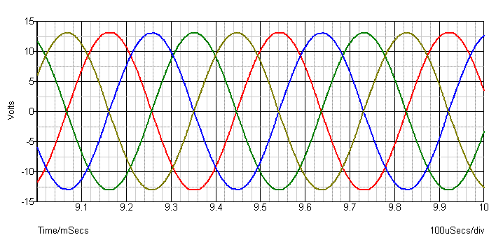
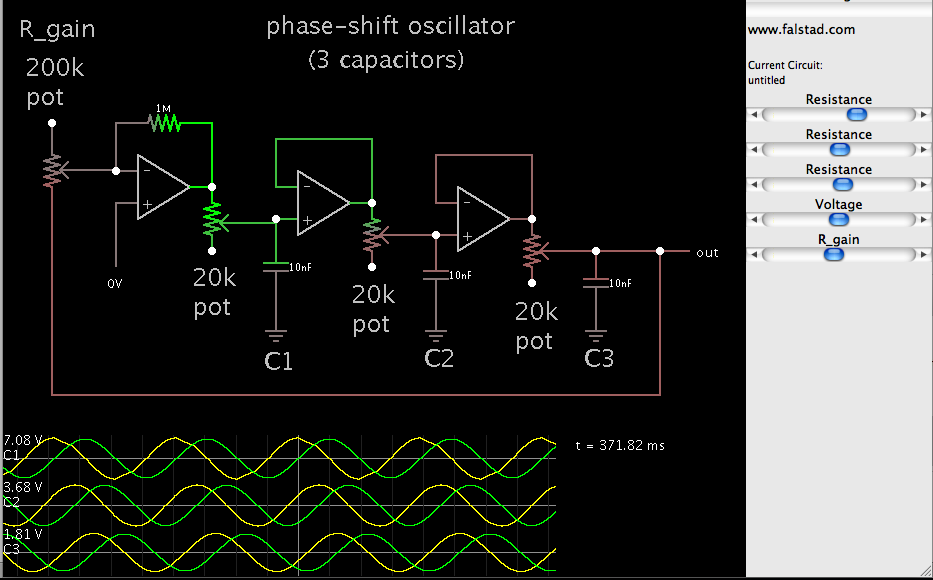
Hey guys, I was just wondering how I would go about controlling 3 potentiometers around a circuit with a single (master) potentiometer. I am making a sine wave generator and I need a way to change 3 different pots, but with the same value (ie. 10k, 10k, 10k). I was thinking of using MOSFETs or BJTs as variable resistors by controlling their gates somehow, but how do i do it?
Thanks")
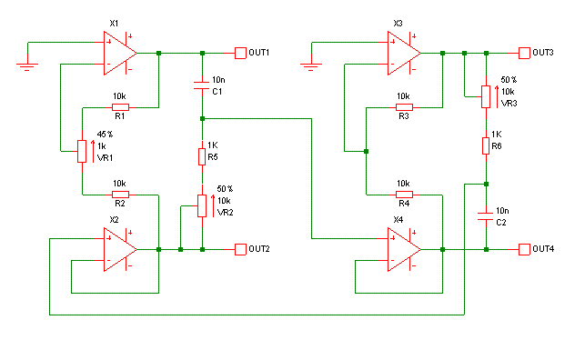
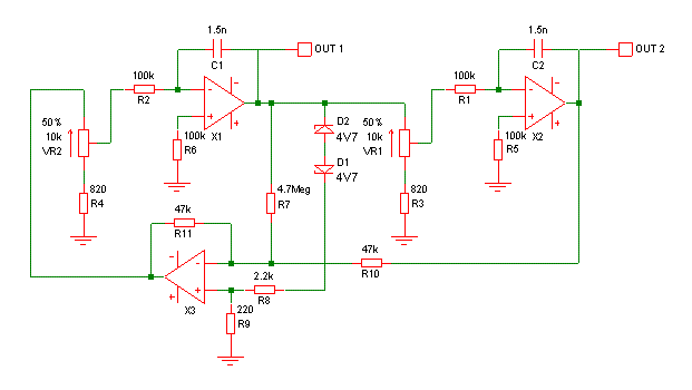
Here is the cct

- - - Updated - - -
Also, i would like the resistor values to be from 6ohms to 10k.
Thanks
Here is the cct
- - - Updated - - -
Also, i would like the resistor values to be from 6ohms to 10k.