Continue to Site

Welcome to EDAboard.com

Welcome to our site! EDAboard.com is an international Electronics Discussion Forum focused on EDA software, circuits, schematics, books, theory, papers, asic, pld, 8051, DSP, Network, RF, Analog Design, PCB, Service Manuals... and a whole lot more! To participate you need to register. Registration is free. Click here to register now.

how to control 24 fans with a pic controller( low cost).

Status
Not open for further replies.

Sajjadkhan

Full Member level 5
Joined
Sep 25, 2010
Messages
307
Helped
17
Reputation
34
Reaction score
16
Trophy points
1,298
Location
Rawalpindi,Pakistan
Activity points
4,199
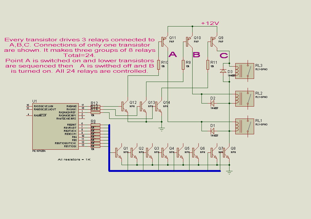
I need to make 24 fans controller. the board has a lcd display and few buttons for settings.

the main issue here is controller I/O pins and cost.

24 pins for fans (220v)
6 pins for lcd,
3 pins for buttons i.e. adjust, up, down ( for setting ON/OFF timer ).

i dont want to use 40 pin controller, 28 pin or less would be fine, then i would also be needing some port expansion method.

so throw me some ideas for a cheapest design possible to workout this problem, i need to make 500 boards with max profit margin.
 

how do you drive your fans?
Relays/Triac/...
Does your fans support variable speed?
 

I take it you would like to set a fan's speed, then leave it to go on to the next fan. You'll make the rounds to all the fans, then start at the first one again?

The idea is to set a fan's speed, then get it to remember what speed it should be running at, unattended.

What about a sample-and-hold circuit?
A given speed corresponds to a volt level.
Charge a capacitor to the desired volt level.
The capacitor holds that level on the high impedance input of a mosfet.
It drives the fan's control device at the proper duty cycle.

Each capacitor will hold the charge only a short while. Therefore you make the rounds every few seconds, to recharge all the capacitors.
 

i think it is better to use multiple controllers, because

* pcb space may be greatly reduced.
* nowadays,cost of the controller is very low
* because of multiple controllers, your design will be intact,means,copying firmware will more difficult.
* bulk order will save your money,means,this case you will need 1000 ic's
* because of uc,you can easily change your i/o ports for pcb design routing adjustment.
* any type of controlling is possible,such as relay driving or phase angle controlling.
* you may communicate both chips serially for saving ports.
* finally,i am using this method for 10 years, using 89c52,without any problems


for above specification,89c52 will do all the job,if you are using 40 pin ic's because it is very cheap lees than $1
 
Last edited:

You can use 1-Wire MicroLAN and digital potentiometers. On that way uC can be smaller, and you can increase number of fans even more. Each fan can have their ID, fans can be located in different places, not just on one place, adjustable speed, memorized status and speed of each fan,......
 

You can use 1-Wire MicroLAN and digital potentiometers. On that way uC can be smaller, and you can increase number of fans even more. Each fan can have their ID, fans can be located in different places, not just on one place, adjustable speed, memorized status and speed of each fan,......

may use modbus & rs485 communication to make such an idea very cost effectively using pic.
 

You can use a shift register for the fan outputs and a keyboard matrix for the buttons. But you must decide if it will be worth the effort!

Shift register usage:
https://www.gammon.com.au/forum/?id=11518

Keyboard matrix:
**broken link removed**
 

Mattrix keypad have max 16 keys, he need 24 fans. Also should check usage of pins on uC to run all of this.
 

how do you drive your fans?
Relays/Triac/...
Does your fans support variable speed?

just relays, no speed control needed. they are asking to turn the 1st fan on for 3 sec and turn it off for about a minute and then in the same way proceed to the next till 24th and then loop back ( one fan at a time ). these fans are blowers to be more specific.

i m adding lcd and timer control to make it more flexible so that in future if some customer ask for variable timer setting then it would be easy for me to reproduce.

- - - Updated - - -

You can use a shift register for the fan outputs and a keyboard matrix for the buttons. But you must decide if it will be worth the effort!

Shift register usage:
https://www.gammon.com.au/forum/?id=11518

Keyboard matrix:
**broken link removed**

i am thinking of shift registers like 74595 and cascade them.

- - - Updated - - -

i think it is better to use multiple controllers, because

* pcb space may be greatly reduced.
* nowadays,cost of the controller is very low
* because of multiple controllers, your design will be intact,means,copying firmware will more difficult.
* bulk order will save your money,means,this case you will need 1000 ic's
* because of uc,you can easily change your i/o ports for pcb design routing adjustment.
* any type of controlling is possible,such as relay driving or phase angle controlling.
* you may communicate both chips serially for saving ports.
* finally,i am using this method for 10 years, using 89c52,without any problems


for above specification,89c52 will do all the job,if you are using 40 pin ic's because it is very cheap lees than $1

getting much out of a controller is more attractive. using 2 controllers i a bad idea because my controller will be soldered to the board and i have to program it through pickit so cant use 8051 or 2 pic controllers.

- - - Updated - - -

You can use 1-Wire MicroLAN and digital potentiometers. On that way uC can be smaller, and you can increase number of fans even more. Each fan can have their ID, fans can be located in different places, not just on one place, adjustable speed, memorized status and speed of each fan,......

i havent worked on 1 wire yet but i have heard that its almost the same as I2c, if true then this means that i have to use 24 devices to communicate with, how would that be low cost?
 

Matrix keypads don't have an upper limit, like if you use a 5x4 matrix (ending up in 9 pins) you can as well have 20 buttons for use, or a 18x18 matrix (36 pins in total) for 324 buttons which can also fit into a 40-pin package mcu easily. I'm not sure I got what you meant here? Or are you actually talking about a ready-made keypad which will hardly be a limitation in implementing one?
 

If you are using relays, among other, you can use one of the following chips:
https://www.ti.com/product/tpl9201
https://www.ti.com/product/tpl9202
https://www.ti.com/product/drv8805
https://www.ti.com/product/drv8806
https://www.ti.com/product/drv8804
**broken link removed**
https://www.maximintegrated.com/datasheet/index.mvp/id/3042
https://www.maximintegrated.com/datasheet/index.mvp/id/4999
https://www.maximintegrated.com/datasheet/index.mvp/id/3564

So you will be able to use a serial interface and you will not need to use an external transistor (mosfet) to drive the relay: cheaper and less clutter on your PCB!
Your pin count usage will be reduced to 3 pin for driving and indefinite number of relays.

I also suggest you to make 3 single boards with 8 relays each one and to "daisy chain" those boards. In a such way even later you can expand your number of output/relays.

Another suggestion is to galvanically insulate (using 3 optocouplers) the board containing the micro/keyboard/display and the power sections (relays driver): your circuit will be safer and less prone to EMC disturbance.
 
Last edited:

you can use an decoder 3*8 and control multiple button with just 3 pin of pic if you are interest tell me to describe it .
 

how you can control output relay's simultaneously using mux...........?


in this case it may work, in future application it will be a bottle neck.
 

so let me teach
you must decoder in reverse and set the buttons in outpot of pic and share the vdd of buttons and joind it to other pin and next step is write sth like below code in your program .
here we have 3*8 decode that is join to port b of pic and the shared pin is in portd.0
for(i=0b000;i<8;i++){
portb=i;
if(portd.0==1) light the fan number x
}
ooo fan1
001 fan2
010 fan3
.
.
.
.
111 fan8

you understand?
this is all about the input control.
why you people are diverting sajjdkhan's question....?
using lcd & 3 button,he can control all the fans.
but the problem is controlling the 24 outputs using 28 pin mcu.
 

so let me teach
you must decoder in reverse and set the buttons in outpot of pic and share the vdd of buttons and joind it to other pin and next step is write sth like below code in your program .
here we have 3*8 decode that is join to port b of pic and the shared pin is in portd.0 [...]

Dear mohammad.ch: I'm not so sure you have understood the requirement of the OP....
 

This simple hardware can full-fill the simple switching requirements,
 

@ALERTLINKS: your solution prevents to drive at the same time more than one random relay. It also require 11 I/O lines.
With the shift register solution you'll use ONLY 3 I/O lines, driving simultaneously even more than 24 relays!
 

I really do not understand why you like to over-complicate things:
in this schematic (drawn in a really hurry, so it can contain some errors) you'll find some suggestions on how to drive an indefinite number of relays using only 3 pins.
The interface is optoisolated just to reduce EMC problems:
SerialRelayDriver.PDF

Please take care that in the schematic there are no bypass capacitors, resistor values should be set according to your application/requirements, no diodes are applied to relays coils (if you are using MIC5891 they are not needed because they are already integrated in the chip) , ...
 
Last edited:

Status
Not open for further replies.

Part and Inventory Search

Welcome to EDABoard.com

Sponsor

Back
Top