Continue to Site

Welcome to EDAboard.com

Welcome to our site! EDAboard.com is an international Electronics Discussion Forum focused on EDA software, circuits, schematics, books, theory, papers, asic, pld, 8051, DSP, Network, RF, Analog Design, PCB, Service Manuals... and a whole lot more! To participate you need to register. Registration is free. Click here to register now.

How to connect the port to the spiral in Sonnet ?

Status
Not open for further replies.

Tom316

Newbie level 1
Joined
Nov 29, 2012
Messages
1
Helped
0
Reputation
0
Reaction score
0
Trophy points
1,281
Activity points
1,291
Hello,

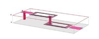
i just started to use Sonnet , and i know that there is a problem with connecting the port to the spiral as when i select view current , i can see that there is no current flow , i would be glad if someone can give me an advice . i have attached my design , it it should be air >copper>taconic>copper>air.

how should the good graph look like ?


Dear Tom
A sonnet is a Closed boundary MOM it needs ports to be on the edge...
so you need to extend the ends of the spiral and then you need to add the edge port...
to nullify the effect of extended line you need to de-embed the extra metal added.

There is a good example (spiral_fine.son)built in to the tool which could clarify your question
 

Hi Tom,
Could you explain your circuit? The picture looks like there is a via shorting out port 1, and there is no DC continuity between port 1 and port 2. Shouldn't there be some connections (wire bonds) connecting the feed lines to the spiral metal?
 

Hi Tom
if you can share your project file I shall try fix your problem...
thnq
 

Just a reminder: Unless you change the boundary conditions of your simulation space Top or Bottom cover, the entire outside of this box will be treated by Sonnet as a PEC boundary. It's convenient if you need to model metal for top and/or bottom ground planes. But if this is not the case in your real model, then you should add layers of air on the top and bottom of your model. That is true even if you change the Top and/or Bottom of your Sonnet simulation box to be Free Space boundaries. You don't want these Free Space boundaries to get too close to your circuit.
 

it it should be air >copper>taconic>copper>air

In this case, you have to increase the thickness of the air layer above and below the Taconic substrate. From your 3D view, this seems to be a very thin layer of air. Use something like 50mm instead. This air thickness is needed, even if you set the top and bottom cover of the simulation box to "free space".

In addition, I agree with Joe_user that the via at the left port is unexpected, and there seem to be gaps between the feedlines and the inductors.
 

Status
Not open for further replies.

Part and Inventory Search

Welcome to EDABoard.com

Sponsor

Back
Top