Continue to Site

Welcome to EDAboard.com

Welcome to our site! EDAboard.com is an international Electronics Discussion Forum focused on EDA software, circuits, schematics, books, theory, papers, asic, pld, 8051, DSP, Network, RF, Analog Design, PCB, Service Manuals... and a whole lot more! To participate you need to register. Registration is free. Click here to register now.

How to connect buck converter with microcontroller?

Status
Not open for further replies.

jimit.shah

Newbie level 3
Joined
Feb 16, 2011
Messages
4
Helped
0
Reputation
0
Reaction score
0
Trophy points
1,281
Activity points
1,319
Hi,

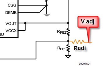
For our project, I need to control a varying input DC signal (5V-60V) and convert it to a stable 5V output. So I am using:

LM5116MH buck converter. I have the circuit diagram which came along with it's datasheet (page 23). The problem is that I need to interface this with a dsPIC33 microcontroller for MPPT. What is the best way to go about this?

Any help would be much appreciated! Thank you!
 

Attachments

  • LM5116MH-datasheet.pdf
    469.9 KB · Views: 139

MPPT maximizes power so if as you stated you desire a stable 5V output then to maximize power the current will need to be varied. Only way that will work is if the load has a large capacity to absorb more power than the PV can supply, i.e. an uncharged battery bank, power grid, etc.

The stable 5V output requirement and MPPT are at odds.

Ray
 
Maximum power point tracker - Wikipedia, the free encyclopedia

**broken link removed**

http://ww1.microchip.com/downloads/en/devicedoc/70155c.pdf

I could be wrong but in order to 'square circles' then I would have to assume that your 'regulated' 5V is in fact some sort of battery or fixed voltage 'sink' in which you are expecting to store or transfer energy from your solar array. As a minimum you might wish to regulate the maximum voltage applied to it. In order to be more sophisticated you would probably wish to control its charging regime. Naturally on the other side of the equation you want to extract the maximum power available from you solar array, without killing the battery/load. That's an interesting one..

I think you end up in a situation whereby you have two things fighting each other and have to decide which one should be 'satisfied' at any particular time.

I don't immediately see how any particular available 'packaged' solution, LM5116, or otherwise 'solves' your problem. For MPPT you would probably need to monitor input voltage and control demand current, based on the sums done by your PIC in order to maximise power delivery.

Without adding extra sensing and control around your selected LM5116.....

and that was your original question.

Genome
 
Hey guys,

Thank you for your replies.

I guess I never explained the situation completely. But basically, we are getting the electrical energy from wave turbines which will be a varying AC signal. This is converted to a DC signal via a vienna rectifier circuit. The rectifier will be interfaced with the dsPIC33 for PFC. Now, this is where I come in. The varying DC signal needs to be corrected for a stable 5Vdc output. According to one of my group mates, I need to apply the MPPT algorithm which doesn't really make sense to me. So I needed your guys' input whether I should even worry about it or not. Also, I am planning to hook up a lead-acid battery to the DC-DC circuit. This will keep the battery charging and the battery can supply a 5Vdc output to the sensors on the other end.
Please tell me if I should do it a different way.

Thank you.
 

That's a little different story with the wind turbines driving a battery charger (the original DC-DC converter mentioned above) and the battery / charger is supplying the 5VDC through I assume an additional DC-DC converter. Then the MPPT may make sense to maximize the charging of the batteries.

With that said, back to your original question of how to interface the DC-DC converter to the microprocessor. You'll need to be able to vary the set point (output voltage) of the converter. Since it's charging a battery the adjustment range will be small and you'll need to limit the max voltage to not overcharge the battery.

You can adjust that voltage a couple of different ways. One way is to use a filtered PWM output to affect the voltage feedback loop of the converter. You can either apply the voltage directly to the loop through a resistor to inject current into the feedback pulling it up or down or put an opamp in the loop and use the PWM voltage to directly offset the feedback voltage. The resistor method requires careful juggling of the values but doesn't affect the loop response. The second method has more flexibility but the opamp must be chosen carefully to not to adversely affect the control loop frequency.

If there is not a PWM available then and I2C or SPI or some other kind of DAC could be used to supply the offset voltage.

You must also monitor the total current supplied by the converter and possibly the current in/out of the battery. There are simple high side current to voltage ICs that would work well.

Now the microprocessor must constantly adjust the DC-DC voltage to maximize the power, V*I , by adjusting the DC-DC output voltage to produce the max power. A simple algorithm could be one that ramps the voltage up and down a small amount while monitoring the power and adjusts the ramping end points to keep the peak power centered in that ramp range. I think you have to do this hunting because I don't believe that point can be calculated directly given the varying wind speed.

Also you'll need to follow the proper charging procedure for whatever type of battery you are using, including charge current limit, charge cut off voltage and float voltage.

I hope this helps you. Let me know if you need more details on controlling the DC-DC converters.

Ray
 

Hi Ray,

Thank you so much for the detailed response. Just to clarify.. the energy is coming from the water wave turbines which will be put in the gulf of mexico.

I get the idea of how to set the algorithm but could you explain how to physically connect the buck converter to the microcontroller? I mean if you look at the circuit in the attached datasheet pdf document (Pg. 22) in my original post, you'll see the input coming in as a 7Vdc to 60Vdc and the output voltage and current as 5Vdc and 7A respectively.

I have no experience of using microcontrollers so that's why I sound really confused about this. Once again, I really appreciate your guys' help!

Hi, as I can see the schematic, 5V 7A simply means the output rating of the converter. LM5116 has internal error amplifier to regulate constant output voltage of 5V with current control mode. If it controls the constant output voltage, not sure how you could control the current at the same time with other controller. Perhaps, the MPPT algo might give the reference signal for the buck converter control.
 

Hi, as I can see the schematic, 5V 7A simply means the output rating of the converter. LM5116 has internal error amplifier to regulate constant output voltage of 5V with current control mode. If it controls the constant output voltage, not sure how you could control the current at the same time with other controller. Perhaps, the MPPT algo might give the reference signal for the buck converter control.

Oh ok. That's was thinking so I'm not going to worry about MPPT.

On the other note, do you think a deep cycled lead acid battery, which will be connected to a UCB hub for a 5V supply, a good option?
 

Hi Ray,

Thank you so much for the detailed response. Just to clarify.. the energy is coming from the water wave turbines which will be put in the gulf of mexico.

I get the idea of how to set the algorithm but could you explain how to physically connect the buck converter to the microcontroller? I mean if you look at the circuit in the attached datasheet pdf document (Pg. 22) in my original post, you'll see the input coming in as a 7Vdc to 60Vdc and the output voltage and current as 5Vdc and 7A respectively.

I have no experience of using microcontrollers so that's why I sound really confused about this. Once again, I really appreciate your guys' help!

This is where you inject the current to adjust the set point of the converter:

91_1298315829.jpg


The resistors are calculated using 3 equations, 3 unknowns. For 2 of the equations you use the min and max required set points and for the third use the amount of current you want flowing through Radj (from the PWM filter).

The voltage from the microprocessor comes from a PWM output. Use an RC to filter the waveform and produce the voltage.

Ray
 
Last edited:

Status
Not open for further replies.

Similar threads

Part and Inventory Search

Welcome to EDABoard.com

Sponsor

Back
Top