designteam
Junior Member level 1
I have a 1Vpp 1Hz repetitive arbitrary wave signal that resides entirely above the DC line. IOW there is no negative-going excursion. This is output from an LM358 inverting op amp buffer powered between +12VDC and ground (0V) rails.
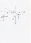
I would like to feed this into an LM358 op amp with a gain of 10 that is powered in a non-standard way as follows. Its "positive" rail is set at 0V. The "ground" rail is set at -12VDC. There is a reason for this, and I do not want to change it.
When I connect the signal from the positively powered buffer op amp to the negatively powered gain stage op amp there is no output, presumably due to the DC level mismatch.
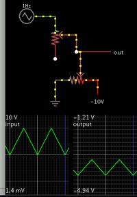
I have seen circuits that shift signals to a higher positive DC level, but not any that shift a positive signal into a negative region. Some level shift circuits also include a capacitor in the signal path, which I would prefer to avoid due to fidelity issues at such a low frequency.
Can someone please provide a working circuit that will enable the gain amp to output the arb wave signal so that it swings between about -10 and 0V? A trimmer adjustment for the DC shift would also be helpful in case I decide to use reduced gain.
This has been a persistent design issue which, due to my limited knowledge, I have not solved so far, either by inquiring online or hours on the bench. Any assistance to get me over this hurdle would be greatly appreciated.


